Method and device for solving mask coloring boundary conflict and computer equipment

A technology of computer equipment and masks, applied in the field of lithography, can solve the problems of low efficiency of the coloring boundary problem, and achieve the effect of improving efficiency and reducing resources

Pending Publication Date: 2022-06-17
DONGFANG JINGYUAN ELECTRON LTD
View PDF0 Cites 0 Cited by
  • Summary
  • Abstract
  • Description
  • Claims
  • Application Information

AI Technical Summary

Problems solved by technology

[0004] In order to solve the problem of inefficiency in dealing with the coloring boundary problem, the present invention provides a method, device and computer equipment for solving mask coloring boundary conflicts

Method used


Image

  • Method and device for solving mask coloring boundary conflict and computer equipment
  • Method and device for solving mask coloring boundary conflict and computer equipment
  • Method and device for solving mask coloring boundary conflict and computer equipment

Examples


Embodiment Construction

[0040] In order to make the objectives, technical solutions and advantages of the present invention clearer, the present invention will be further described in detail below with reference to the accompanying drawings and implementation examples. It should be understood that the specific embodiments described herein are only used to explain the present invention, but not to limit the present invention.

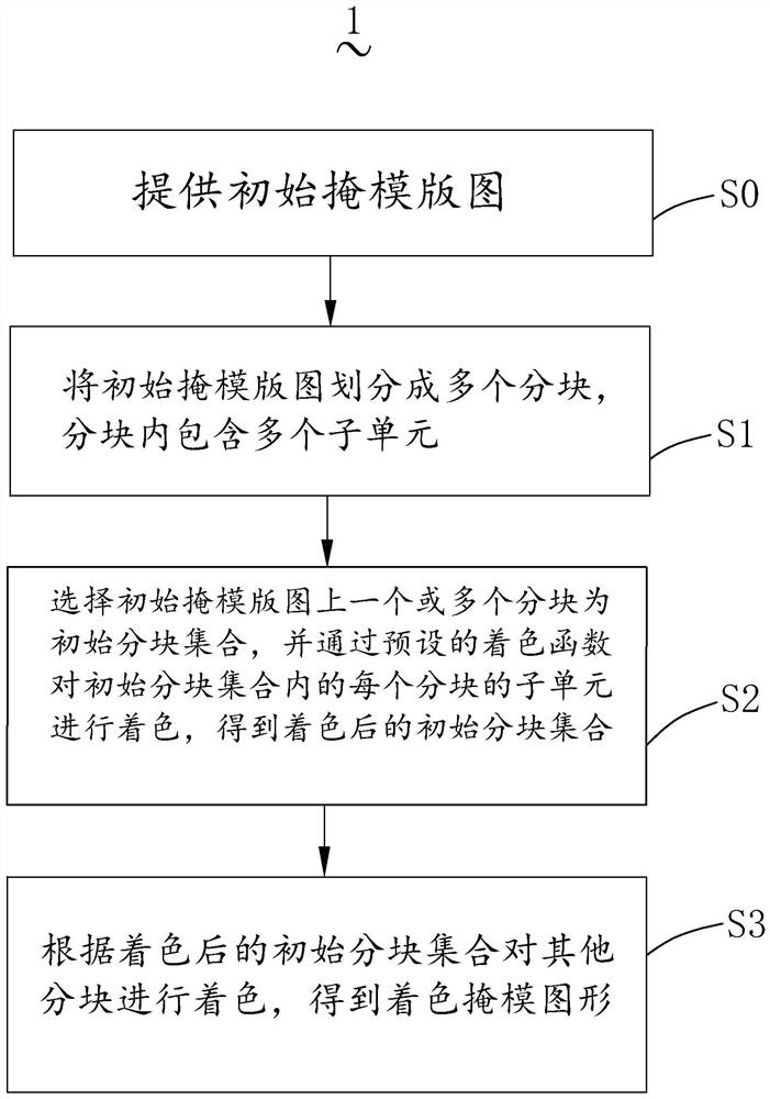
[0041] please combine figure 1 and figure 2 , the first embodiment of the present invention provides a method 1 for resolving coloring boundary conflicts, the method 1 includes the following steps:

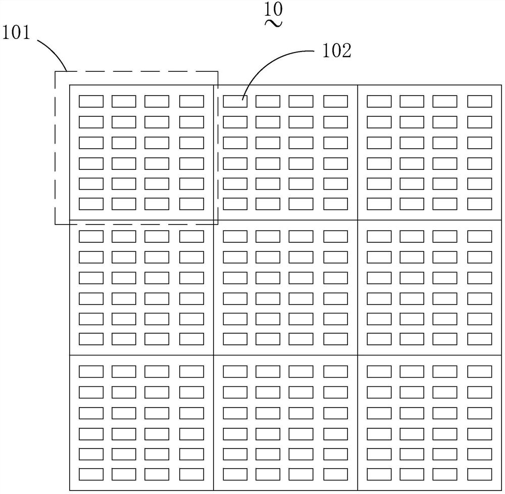
[0042] S0: Provide initial mask layout 10;

[0043] S1: Divide the initial mask layout into a plurality of sub-units 101, the sub-units include a plurality of sub-units 102, and the plurality of sub-units include preset key sub-units; (It is understood that the following involves coloring the sub-units. Note, in fact, the sub-units in the block are colored)

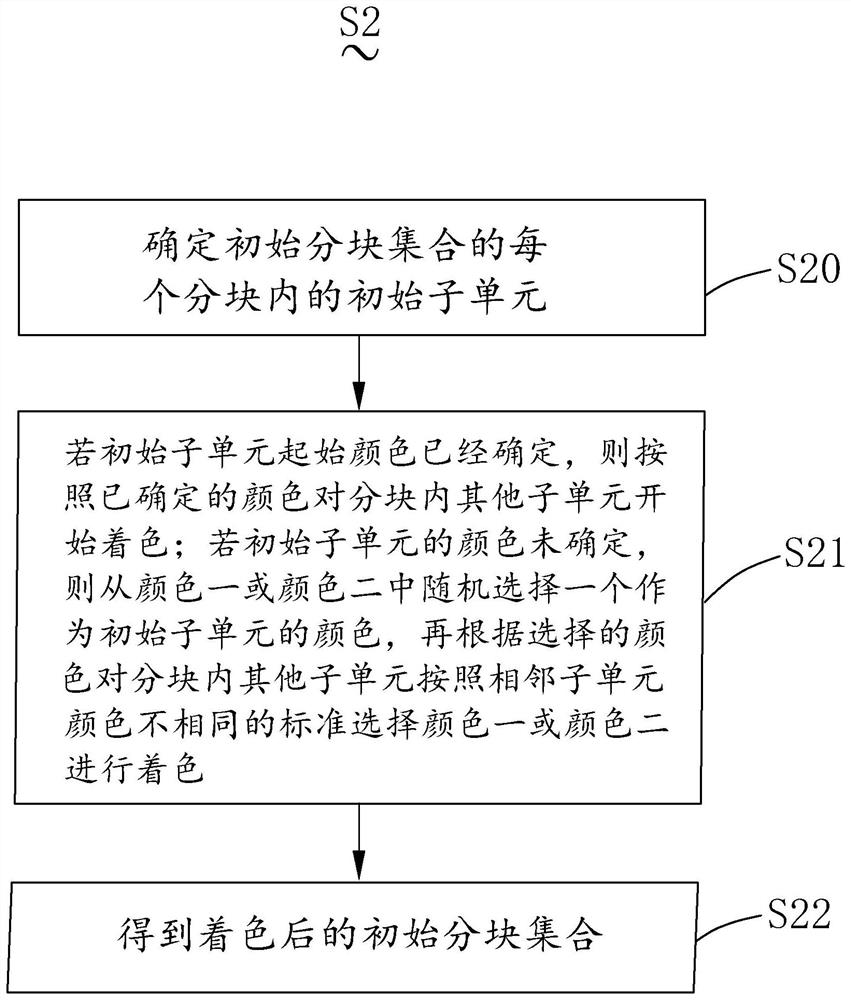
[0044] S2: Select...


PUM


Abstract

The invention relates to the technical field of photoetching, in particular to a method and device for solving coloring boundary conflicts and computer equipment, and the method comprises the following steps: S0, providing an initial mask pattern; the method comprises the steps that S1, an initial mask plate graph is divided into a plurality of blocks, each block comprises a plurality of subunits, and each block comprises an initial subunit and a key subunit; s2, selecting a predetermined area of the initial mask plate graph as an initial block set, the initial block set comprising at least one block, and coloring a subunit of each block in the initial block set through a preset coloring function to obtain a colored initial block set; and S3, coloring other blocks through the coloring function and the key subunit of each block in the initial block set after coloring to obtain a colored mask pattern. According to the method provided by the invention, the efficiency of solving the coloring boundary conflict problem is improved.

Description

【Technical field】 [0001] The present invention relates to the technical field of lithography, and in particular, to a method for resolving coloring boundary conflicts. 【Background technique】 [0002] Photolithography is one of the core technologies for the manufacture of very large scale integrated circuits. The photolithography system uses a light source to illuminate the reticle, and the integrated circuit layout on the mask is imaged onto the photoresist through a projection objective lens. With the increase of the scale of integrated circuits and the improvement of the degree of integration, the feature size of electronic devices continues to shrink, the requirements for integrated circuit manufacturing processes continue to increase, and the requirements for lithography resolution in chip manufacturing are also getting higher and higher. When the logic chip is smaller than At 28nm, if an extreme ultraviolet (EUV) lithography machine is not used, it is necessary to use D...

Claims


Application Information

Patent Timeline
Patent Type & Authority Applications(China)
IPC IPC(8): G06F30/392G06T11/00G03F7/20
CPCG06F30/392G06T11/001G03F7/70425
Inventor 陈运张生睿
Owner DONGFANG JINGYUAN ELECTRON LTD
Why Eureka
Try Eureka