
Spinning spindle assembly

A component and spindle technology, which is applied in the field of the driving mechanism of the spindle of the spinning frame, can solve the problems of high linear speed noise of the spindle belt, harsh production environment, unfavorable high-speed operation of the spindle, etc., so as to increase the limit speed, prolong the life of the spindle, and improve the working environment. Effect

Pending Publication Date: 2022-06-21
徐时平
View PDF0 Cites 0 Cited by
  • Summary
  • Abstract
  • Description
  • Claims
  • Application Information

AI Technical Summary

Problems solved by technology

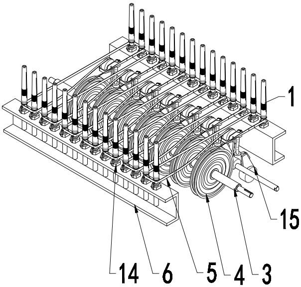
[0005] When the above-mentioned spindle 14 rotates at high speed, in addition to bearing the axial gravity from the spindle itself and the yarn bobbin, it also needs to bear the lateral force brought by the drive of the spindle belt, so that the spindle always deviates to one side, which is not conducive to the high-speed operation of the spindle. The high linear speed of the spindle tape will generate a lot of noise, making the production environment relatively harsh

Method used


Image

  • Spinning spindle assembly
  • Spinning spindle assembly
  • Spinning spindle assembly

Examples


Embodiment 1

[0036] The outer surface of the drive disk casing 812 is provided with a transmission part. In this embodiment, the transmission part is a concave ring 8121 that can be embedded in the transmission belt. The spindle belt of the driving mechanism can be embedded in this concave ring 8121 and cling to the outer wall of the drive disk casing 812 , the driving disk casing 812 is driven to rotate through the spindle tape, so that the driving disk 811 is rotated.

[0037] A bearing 84 is arranged in the inner cavity of the lower part of the drive disk casing 812 , and the bearing 84 is sleeved outside the fixed disk casing 832 .

[0038] Thrust bearing 841 is also arranged in the inner cavity of the bottom end of the drive disk casing 812, and the thrust bearing 841 is limited by a fixed cap 843 and threaded on the inner cavity of the fixed disk casing 832 with a bolt 842, so that the drive disk casing The 812 will not move axially on the fixed disk sleeve.

[0039] The fixed plate...

Embodiment 2

[0057] Except this embodiment and embodiment 1 fixed plate is fixed on the dragon tendon 6 or other textile mechanism, can also use other commonly used two object fixing ways to fix the fixed plate on the dragon tendon 6, no longer here List them all.

[0058] The structure of the drive disc assembly of this embodiment is identical to that of the drive disc of Embodiment 1 except that the number of drive magnetic grains uniformly distributed along the circumference of the drive disc and the screw thread on the outer circumference of the drive disc are the same. The drive disc of this embodiment is 77 Twelve driving magnetic particles 82 are evenly distributed along its circumference.

[0059] Four driven magnetic particles 89 are installed on the driven disk of the spindle assembly of this embodiment, and the rest are identical to Embodiment 1. The lower part of the spindle rod is inserted into the bearing, and the spindle rod can rotate coaxially around the fixed disk.

[00...


PUM


Abstract

The spinning spindle assembly comprises a driving piece assembly, a fixing piece assembly and a spindle assembly, the upper portion of a driving sleeve of the driving piece assembly is perpendicularly fixed to the center of a driving piece, a transmission part capable of enabling the driving sleeve to rotate is arranged on the outer surface of the driving sleeve, a through hole communicated with an inner cavity of the driving sleeve is formed in the center of the driving piece, and driving magnets are evenly distributed on the driving piece along the circumference. The upper portion of a fixing sleeve of the fixing part assembly is vertically fixed to the center of a fixing part, a through hole is formed in the center of the fixing part and communicated with an inner cavity of the sleeve to form an inner channel, and magnetizers are evenly distributed on the fixing part along the circumference. A spindle of the spindle assembly penetrates through the driven piece and is fixed to the driven piece, and driven magnets are evenly distributed on the driven piece along the circumference. The lower portion of the spindle blade is rotatably connected to the inner channel and limits the driven piece, the driving sleeve is sleeved and limited on the fixed sleeve in a rolling mode, the close ends of the driven magnets and the driving magnets are opposite in polarity and conduct magnetism through the magnetism conducting column, the number of the driving magnets is larger than that of the driven magnets, and the driving piece, the fixed piece and the driven piece are all made of magnetism isolating materials.

Description

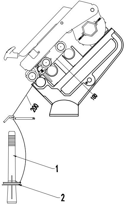
technical field [0001] The invention relates to a component of a spinning frame, in particular to a driving mechanism of a spinning frame spindle. Background technique [0002] like figure 1 As shown, after the fiber strand 100 of the existing spinning mechanism is drawn, the yarn 200 is formed by rotating and twisting the spindle tube 1, while the spindle tube 1 rotates with the rotation of the spindle 14, and the spindle 14 is rotated by the rotating mechanism. driven to rotate. [0003] like figure 2 As shown, the rotating mechanism of the existing spindle tube 1 generally includes a main shaft 3, a rolling plate 4, a spindle 14, a dragon bar 6, and a spindle belt 5. The spindle tube 1 is set on the spindle 14, and the spindle 14 is installed on the dragon bar 6. The belt 5 is wrapped on the spindle 14, the spindle belt 5 is driven by the roller 4, the roller 4 is driven by the main shaft 3, the tension of the spindle belt 5 is provided by the weight 15, the main shaf...

Claims


Application Information

Patent Timeline
Patent Type & Authority Applications(China)
IPC IPC(8): D01H1/24D01H1/26
CPCD01H1/24D01H1/26
Inventor 徐时平
Owner 徐时平
Learn More