Auxiliary welding device for pile tip of highway PHC pipe pile

A PHC pipe pile and auxiliary device technology, applied in auxiliary devices, welding/cutting auxiliary equipment, welding equipment and other directions, can solve the problems of air mixing, time-consuming and laborious pipe pile docking work, and affecting the construction quality of the pile body.

Pending Publication Date: 2022-06-24
CHINA FIRST HIGHWAY ENG +1
View PDF13 Cites 0 Cited by
  • Summary
  • Abstract
  • Description
  • Claims
  • Application Information

AI Technical Summary

Problems solved by technology

[0003] In the construction process of PHC pipe piles and pile point piles, the construction method of welding piles is generally used. The welding quality is particularly important. When the wind speed is too high, the airflow and cold air will cause the welding arc to be extremely unstable. Air is mixed into the protective pores in the middle, and honeycomb welds are easily formed during welding, resulting in the overall weld strength not meeting the design requirements, and the gap strength is insufficient, and weld cracking is very easy to occur in the later stage. Therefore, welding in an open environment will eventually affect the air flow. The overall construction quality of the pile body. At the same time, the PHC pipe pile and the pile tip are often deviated during the docking process, which requires manual adjustments for many times. It is time-consuming and labor-intensive, and the welding device can only be welded by hand during welding. The manual hand will be sore and trembling after a long time, resulting in the overall weld strength of the welding place not meeting the design requirements, the gap strength is insufficient, and the weld cracking phenomenon is very easy to occur later. Therefore, it is urgent to solve the problem of welding stability. Based on the existing technical deficiencies, the present invention designs a welding auxiliary device for highway PHC pipe piles.

Method used


Image

  • Auxiliary welding device for pile tip of highway PHC pipe pile
  • Auxiliary welding device for pile tip of highway PHC pipe pile
  • Auxiliary welding device for pile tip of highway PHC pipe pile

Examples


Embodiment Construction

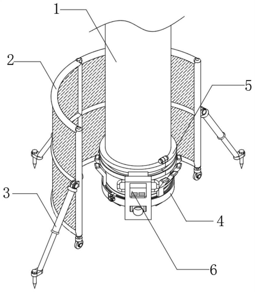
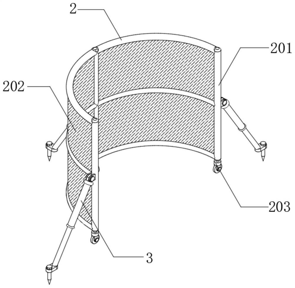
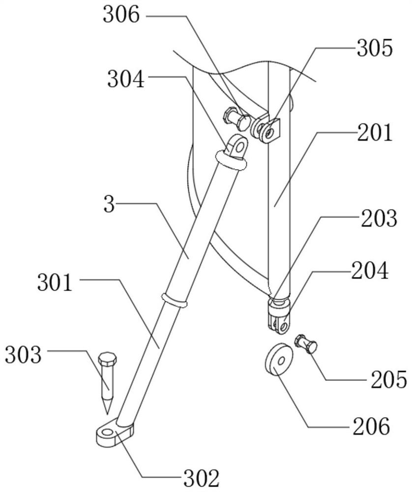
[0031] The embodiment of the present invention discloses an auxiliary device for welding PHC pipe pile tip of expressway, such as Figure 1-8As shown, it includes a PHC pipe pile body 1, one side of the PHC pipe pile body 1 is provided with a second fixing ring 2, one side of the second fixing ring 2 is provided with a support rod 3, and the lower surface of the PHC pipe pile body 1 is provided with a The pile tip 101, the lower surface of the pile tip 101 is provided with a guiding mechanism 4, the outer surface of the PHC pipe pile body 1 is provided with a clamping mechanism 6, and the guiding mechanism 4 is provided to facilitate the bearing of the guiding block 102;

[0032] Refer to the attached Figure 7 , 8 As shown, the device also includes a bearing mechanism 5, which is arranged on one side of the PHC pipe pile body 1, and the bearing mechanism 5 includes a bearing ring 501, a bearing groove 502 and a connecting arc block 503, and the bearing ring 501 is arranged o...


PUM


Abstract

The invention discloses a highway PHC pipe pile tip welding auxiliary device, and relates to the field of PHC pipe piles. The highway PHC pipe pile tip welding auxiliary device comprises a PHC pipe pile body, a second fixing ring is arranged on one side of the PHC pipe pile body, a supporting rod is arranged on one side of the second fixing ring, a pile tip is arranged on the lower surface of the PHC pipe pile body, and a guide mechanism is arranged on the lower surface of the pile tip. A clamping mechanism is arranged on the outer surface of the PHC pipe pile body, and the bearing mechanism is arranged on one side of the PHC pipe pile body. According to the highway PHC pipe pile tip welding auxiliary device, by arranging the clamping mechanism, welding of a PHC pipe pile and a pile tip can be conveniently assisted, by arranging the guide block, connection between the PHC pipe pile body and the pile tip can be more attached, and by arranging the windproof plate, the highway PHC pipe pile tip welding auxiliary device is convenient to use.

Description

technical field [0001] The invention relates to the technical field of PHC pipe piles, in particular to an auxiliary device for welding PHC pipe piles of expressways. Background technique [0002] PHC pipe piles are prestressed high-strength concrete pipe piles. It adopts the pre-tensioned prestressed centrifugal molding process, and after 10 atmospheric pressure (about 1.0Mpa) and steam curing at about 180 ℃, a hollow cylindrical concrete prefabricated component is made. The standard section length is 10m and the diameter ranges from 300mm~ 800mm, concrete strength grade ≥ C80. [0003] In the construction process of PHC pipe piles and pile tip piles, the construction method of welding piles is generally used. The welding quality is particularly important. When the wind speed is too large, the airflow and cold air will cause the welding arc to be extremely unstable. The air is mixed into the middle protective air hole, and it is easy to form a honeycomb weld during weldin...

Claims


Application Information

Patent Timeline
Patent Type & Authority Applications(China)
IPC IPC(8): B23K37/04B23K37/00E02D5/72
CPCB23K37/0426B23K37/00E02D5/72
Inventor 靳连贺杨洋潘登王佳文蒲耀东董亮
Owner CHINA FIRST HIGHWAY ENG
Why Eureka
Try Eureka