Demolding device for foam plastic molding machine and demolding method thereof

A demolding device and molding machine technology, applied in the field of foamed plastic products, can solve the problems of easy breakage, increased damage rate of foamed plastics, broken and perforated foamed plastics, etc., so as to improve the integrity rate, avoid force clamping, reduce stress The effect of force damage

Pending Publication Date: 2022-06-24
沭阳亿彩泡塑有限公司
View PDF1 Cites 0 Cited by
  • Summary
  • Abstract
  • Description
  • Claims
  • Application Information

AI Technical Summary

Problems solved by technology
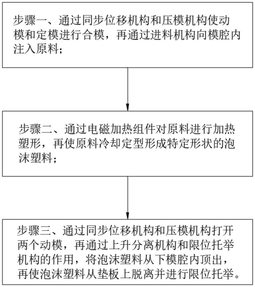
[0004] In the prior art, after cavity molding of foamed plastics, it is necessary to take out the foamed plastics from the mold. After the foamed plastics are cooled and molded at high temperature in the mold, it is easy to stick to the inner wall of the cavity mold. Most of the traditional demoulding methods use ejector pins. Eject the foamed plastic from the cavity mold. Since the foamed plastic is a polymer material containing a large number of air bubbles, it is light in weight and easy to break. The extrusion of a small area of ​​the ejector pin will easily cause fragmentation and perforation of the foamed plastic, resulting in damage to the foamed plastic. , affecting the demoulding effect of foamed plastics, resulting in an increase in the damage rate during foamed plastics processing

Method used


Image

  • Demolding device for foam plastic molding machine and demolding method thereof
  • Demolding device for foam plastic molding machine and demolding method thereof
  • Demolding device for foam plastic molding machine and demolding method thereof

Examples


Embodiment approach

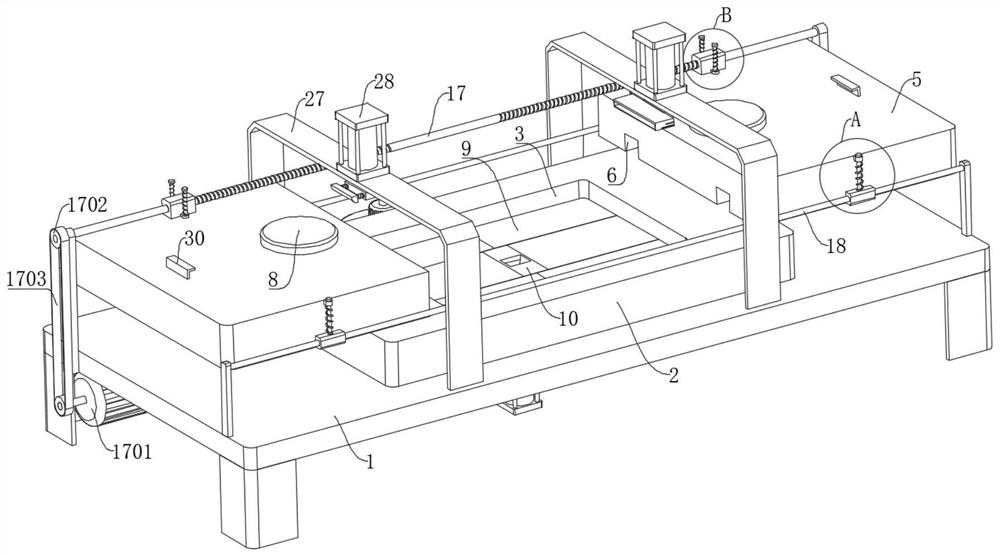
[0049] As an embodiment of the present invention, the opening blocking mechanism includes a first cylinder 15 , the first cylinder 15 is fixedly installed at the bottom of the feed shell 10 , and the end of the telescopic section of the first cylinder 15 penetrates through the bottom of the feed shell 10 and After extending to the inside of the feeding cavity 11, a blocking block 16 is fixedly connected, and the blocking block 16 is adapted to the injection port of the feeding cavity 11; during operation, when the feeding is finished, the first cylinder 15 is activated, and the first cylinder The output shaft of 15 drives the blocking block 16 to move, and the blocking block 16 moves upward along the feeding cavity 11. The top of the blocking block 16 is flush with the top of the opening of the feeding cavity 11, thereby blocking the opening of the feeding cavity 11. And make the top of the feeding shell 10 smooth and flat, while ensuring the feeding, it is beneficial to keep t...


PUM


Abstract

The invention relates to the technical field of foam plastic products, in particular to a demolding device for a foam plastic forming machine and a demolding method thereof.The demolding device comprises a machining table, a fixed mold is fixedly connected to the top of the machining table, a lower mold cavity is formed in the top of the fixed mold, a through hole is formed in the portion, below the fixed mold, of the surface of the machining table, and a feeding mechanism is connected to the bottom of the fixed mold; two movable dies are connected to the upper portion of the fixed die through a synchronous displacement mechanism, upper die cavities are formed in the bottoms of the movable dies, and a die pressing mechanism is connected to the machining table; the jacking area of the bottom of foamed plastic is increased through the base plates, so that the situation that the foamed plastic is broken and perforated due to the fact that the contact area is too small during jacking is reduced, the two base plates are far away from each other, the foamed plastic is lifted through the limiting lifting mechanism in the far-away process, and the situation that the foamed plastic is damaged due to stress in the demolding process is reduced; and the perfectness ratio of the foamed plastic in the demolding process is improved.

Description

technical field [0001] The invention relates to the field of foamed plastic products, in particular to a demolding device for a foaming molding machine and a demolding method thereof. Background technique [0002] Foamed plastic is a type of polymer material formed by a large number of gas micropores dispersed in solid plastics. It has the characteristics of light weight, heat insulation, sound absorption, shock absorption, etc., and its dielectric properties are better than matrix resins. Plastic is a polymer material with plastic as the basic component and contains a large number of air bubbles, so it can also be said to be a composite plastic with gas as a filler. Compared with pure plastic, it has many excellent properties, such as light weight, high specific strength, shock load absorption, good thermal and sound insulation properties, etc. Therefore, it has been widely used in industry, agriculture, construction, transportation and other fields. [0003] Some patent ...

Claims


Application Information

Patent Timeline
IPC IPC(8): B29C33/44B29C33/22B29C44/34
CPCB29C33/44B29C33/22B29C44/35
Inventor 纪德江王召君
Owner 沭阳亿彩泡塑有限公司
Why Eureka
Try Eureka