End face tooth part connected power transmission device

A technology of power transmission device and face teeth, which is applied to vehicle components, transportation and packaging, wheel hubs, etc., and can solve problems such as abnormal starting noise, long splines, and assembly difficulties

Pending Publication Date: 2022-06-24
C&U CO LTD +1
View PDF8 Cites 0 Cited by
  • Summary
  • Abstract
  • Description
  • Claims
  • Application Information

AI Technical Summary

Problems solved by technology

The traditional connection method has a long spline, which is not easy to process and difficult to assemble
Due to machining errors or wear during driving, there will be a gap between the driving element and the hub bearing

Method used


Image

  • End face tooth part connected power transmission device
  • End face tooth part connected power transmission device
  • End face tooth part connected power transmission device

Examples


Embodiment Construction

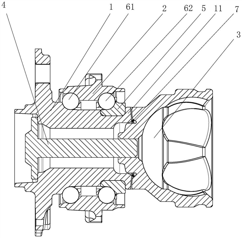
[0020] Embodiments of the power transmission device connected by end face teeth of the present invention are as follows figure 1 , Figure 5 , Image 6 and Figure 7 As shown: including outer ring 2, inner ring 1, universal joint 3 and locking bolt 4, a first raceway is set between the outer ring 2 and inner ring 1, and a first raceway is set in the first raceway Roller 61, the inner ring 1 is also equipped with an insert ring 5, a second raceway is formed between the insert ring 5 and the outer ring 2, and a second roller 62 is arranged in the second raceway, so The edge of the inner ring 1 corresponding to the position of the bezel 5 is provided with a curling flange abutting against the universal joint 3, and straight teeth are arranged along the circumferential direction on the abutting surfaces of the curling flange and the universal joint 3 respectively. 7. The universal joint 3 and the curling flange form the torque transmission between the inner ring 1 and the unive...


PUM


Abstract

The invention discloses an end face tooth part connection power transmission device which comprises an outer ring, an inner ring, a universal joint and a locking bolt, a first roller path is arranged between the outer ring and the inner ring, a first roller is arranged in the first roller path, an embedded ring is further arranged on the inner ring in a matched mode, a second roller path is formed between the embedded ring and the outer ring, and a second roller path is arranged in the second roller path. A second roller is arranged in the second roller path, a hemming flange abutting against the universal joint is arranged at the position, corresponding to the embedded ring, of the edge of the inner ring, and straight teeth are distributed on the abutting face of the hemming flange and the universal joint in the circumferential direction. The universal joint and the hemming flange form torque transmission between the inner ring and the universal joint through mutual meshing of the straight teeth, the head portion of the locking bolt abuts against the side wall of the inner ring, and the rod portion of the locking bolt penetrates through an inner hole of the inner ring and then is in threaded fit with the universal joint. The power transmission device is compact in structure, lower in overall weight, high in installation precision and stable in power transmission.

Description

technical field [0001] The invention relates to the technical field of hub bearings, in particular to a power transmission device connected by end-face gears. Background technique [0002] The hub bearing of the drive wheel is usually connected with the vehicle drive element (spherical cage shaft) using a pair of inner and outer splines to transmit the power of the vehicle. The traditional connection method is provided with long splines, which is not easy to process and difficult to assemble. Due to machining errors or wear during driving, there will be a gap between the driving element and the hub bearing during the operation of the vehicle, which makes the vehicle driving element and the hub different from the axis of rotation, and it is easy to generate abnormal noise at startup, making the power transmission Not smooth. At the same time, the national government has increasingly stringent requirements on vehicle emissions, as well as the application of new high-torque t...

Claims


Application Information

Patent Timeline
IPC IPC(8): B60B27/00
CPCB60B27/0031B60B27/0021B60B27/001B60B27/0078Y02E10/72
Inventor 胡晟
Owner C&U CO LTD
Why Eureka
Try Eureka