
Corrugated pipe filling valve structure

A bellows and valve technology, applied in the field of bellows filling valve structure, can solve the problems of complex bolt and gasket connection and sealing structure, difficult welding of bellows, poor sealing reliability, etc., and achieves simple structure, fewer components, and easy operation. Effect

Pending Publication Date: 2022-06-24
济南新材料产业技术研究院
View PDF0 Cites 0 Cited by
  • Summary
  • Abstract
  • Description
  • Claims
  • Application Information

AI Technical Summary

Problems solved by technology

The existing bellows valve driving mechanism and anti-rotation mechanism have complex structures, many parts, and difficult assembly; the bolt and gasket connection sealing structure at the valve body and bonnet is complex, and the sealing reliability is poor; when the bellows is welded to the valve stem and bonnet When the bellows is a thin-walled structure, there is a large thickness difference between the valve stem and the valve cover, and the valve structure makes the welding more inconvenient, which leads to great difficulties in the bellows welding; although the bellows valve can solve There is a problem with the outer seal of the valve, but the pressure bearing capacity is poor

Method used


Image

  • Corrugated pipe filling valve structure

Examples


Embodiment Construction

[0022] It should be noted that the following detailed description is exemplary and intended to provide further explanation of the invention. Unless otherwise defined, all technical and scientific terms used herein have the same meaning as commonly understood by one of ordinary skill in the art to which this invention belongs.

[0023] It should be noted that the terminology used herein is for the purpose of describing specific embodiments only, and is not intended to limit the exemplary embodiments according to the present invention. As used herein, unless the invention clearly dictates otherwise, the singular is intended to include the plural as well, and it is also to be understood that when the terms "comprising" and / or "including" are used in this specification, Indicate the presence of features, steps, operations, devices, components and / or combinations thereof;

[0024] Explanation of terms: The isovolume in the "isovolume deformation chamber" in this embodiment refers ...


PUM


Abstract

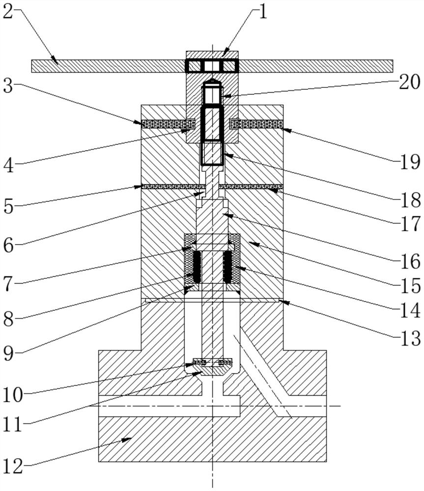
The invention discloses a corrugated pipe filling valve structure which comprises a driving handle, a driving nut, a valve rod, a valve cover and a valve body, the driving handle is connected with the driving nut, the driving nut is in threaded fit with the valve rod, a first pin hole is formed in the valve cover, and a first limiting pin penetrates through the first pin hole to be inserted into the driving nut; a second pin hole is further formed in the valve cover, and a second limiting pin penetrates through the second pin hole to limit rotation of the valve rod. The driving mechanism is composed of a driving nut, a driving handle and a limiting pin, the driving handle drives the driving nut to rotate, the limiting pin limits vertical movement of the driving nut, and the driving nut achieves vertical movement of the valve rod through threads. The driving mechanism is simple in structure, few in component parts, convenient to assemble and low in manufacturing cost.

Description

technical field [0001] The invention belongs to the technical field of valves, in particular to a bellows filling valve structure. Background technique [0002] Bellows valves generally include main components such as drive mechanism, valve body, valve cover, valve stem, valve core, bellows, and anti-rotation mechanism. The existing bellows valve drive mechanism and anti-rotation mechanism have complex structures, many parts and components, and are difficult to assemble; the bolts and gaskets between the valve body and the bonnet have complex connection and sealing structures, and the sealing reliability is poor; the bellows is welded with the valve stem and the bonnet. When the bellows is a thin-walled structure, there is a large thickness difference with the valve stem and the valve cover. In addition, the valve structure problem makes welding more inconvenient, resulting in greater difficulties in welding the bellows; although the bellows valve can be solved There is a p...

Claims


Application Information

Patent Timeline
Patent Type & Authority Applications(China)
IPC IPC(8): F16K31/50F16K31/60F16K1/50F16K41/10F16K27/08F16K27/10
CPCF16K31/508F16K31/60F16K1/50F16K41/10F16K27/08F16K27/102
Inventor 王刚施月杰明宇
Owner 济南新材料产业技术研究院
Learn More