A differential displacement sensor detection device and detection method

A displacement sensor and detection device technology, which is applied in the direction of measuring devices, electromechanical devices, and electrical devices, etc., can solve the problem of low detection accuracy and achieve the effect of improving accuracy and realizing detection

Active Publication Date: 2022-08-05
SHANDONG ZHANGQIU HUADONG BLOWER
View PDF27 Cites 0 Cited by
  • Summary
  • Abstract
  • Description
  • Claims
  • Application Information

AI Technical Summary

Problems solved by technology

[0008] In view of this, in order to solve the above-mentioned problems, an embodiment of the present invention provides a differential displacement sensor detection device, by fixing the first sensor probe and the second sensor probe on the same side of the workpiece to be measured, and The probes of the two are located on the same detection surface, which solves the technical problem of low detection accuracy of the existing eddy current displacement sensor detection device

Method used


Image

  • A differential displacement sensor detection device and detection method
  • A differential displacement sensor detection device and detection method
  • A differential displacement sensor detection device and detection method

Examples


Embodiment 1

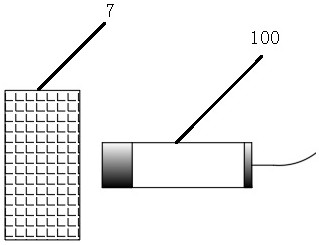
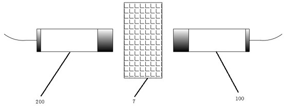
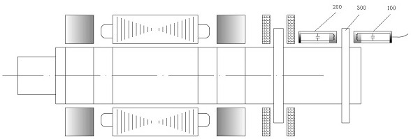
[0043] Please refer to Figure 4 to Figure 6 As shown, a differential displacement sensor detection device in this embodiment includes a workpiece to be tested 7, a displacement sensor assembly and a signal processing unit, wherein a rotor thrust plate is fixed on the workpiece to be tested 7 13. Left and right axial magnetic bearings (12, 14) are provided on both sides of the rotor thrust plate 13. The displacement sensor assembly includes a first sensor probe 1, a second sensor probe 4, and a signal processing unit connected to the first sensor probe and the second sensor probe; wherein, the first sensor probe 1 and the second sensor probe 4 are both It is fixedly arranged on the same side of the workpiece 7 under test, and the probes of the two are located on the same detection surface, and the signal processing unit is used for conditioning and analyzing the voltage signals output by the first sensor probe and the second sensor probe.

[0044] Specifically, a differential...

Embodiment 2

[0048] combine Figure 7 The schematic diagram of the principle framework of the signal processing unit shown, this embodiment is based on the first embodiment, as a specific implementation, the signal processing unit in this embodiment includes an excitation circuit, a coupling resistor, a multiplier and a low-pass filter. The excitation circuit generates a high-frequency signal and sends it to the parallel resonant circuit composed of the inductance coil and the capacitor through the coupling resistance Rs. The amplitude of the high-frequency signal of the probe coil caused by the change of the measured workpiece position is equivalent to modulating the measured workpiece position change to the excitation. On the signal, the multiplier multiplies the modulated signal and the excitation signal, and outputs a pair of signals with changed phases to the low-pass filter. After the amplitude-modulated signal passes through the low-pass filter, the high-frequency carrier signal is ...

Embodiment 3

[0055] like Figure 9 A differential displacement sensor detection method shown in this embodiment includes the differential displacement sensor detection device described in any one of the first embodiment and the second embodiment, and the detection method includes the following steps:

[0056] When the measured workpiece is shifted to the right, the voltage signal output by the first sensor probe gradually increases, and the voltage signal output by the second sensor probe gradually decreases, and the electromagnetic attraction force of the right axial magnetic bearing increases. , the electromagnetic suction force of the left axial magnetic bearing is reduced, so that the measured workpiece is adjusted to the left.

[0057] like Figure 10 A differential displacement sensor detection method shown in this embodiment includes the differential displacement sensor detection device described in any one of the first embodiment and the second embodiment, and the detection method...


PUM


Abstract

The invention provides a differential displacement sensor detection device and detection method, which are used to measure the axial vibration of a rotor rotating at high speed, and include a workpiece to be measured, a displacement sensor assembly and a signal processing unit; wherein, the displacement sensor assembly includes a first a sensor probe, a second sensor probe and a signal processing unit connected to the first sensor probe and the second sensor probe, and the first sensor probe and the second sensor probe are fixedly arranged in the same part of the workpiece to be tested On the other hand, the signal processing unit is used for conditioning and analyzing the voltage signals output by the first sensor probe and the second sensor probe. The first sensor probe and the second sensor probe are fixedly arranged on the same side of the workpiece to be tested, and the probes of the two are located on the same detection surface, which effectively realizes differential control detection and greatly improves the detection accuracy.

Description

technical field [0001] The invention relates to the technical field of magnetic levitation motor detection, in particular to a differential displacement sensor detection device and a detection method. Background technique [0002] A very important part of the performance of the magnetic levitation motor depends on the characteristics of the displacement sensor device. To measure the position of a moving rotor, a non-contact eddy current displacement sensor is required, which can measure a rotating surface. [0003] At present, there are three main ways to use the eddy current displacement sensor detection device: [0004] The first is to use an eddy current displacement sensor alone, such as figure 1 As shown in the figure, if an ordinary eddy current displacement sensor 100 is used, which is installed and placed on one side of the workpiece 7 to be measured, the measurement accuracy of the sensor will be disturbed by factors such as temperature, noise, coupling error, etc....

Claims


Application Information

Patent Timeline
Patent Type & Authority Patents(China)
IPC IPC(8): G01B7/02H02K11/21H02N15/00
CPCG01B7/02H02K11/21H02N15/00
Inventor 陈李成李大同刘晋
Owner SHANDONG ZHANGQIU HUADONG BLOWER
Why Eureka
Try Eureka