
High-frequency vibration fatigue test device for thin-wall blade parts

A high-frequency vibration and fatigue testing technology, applied in vibration testing, workpiece clamping devices, testing of machine/structural components, etc. Unable to multi-directional high-frequency vibration and other problems, to achieve the effect of improving clamping stability

Active Publication Date: 2022-06-24
HENAN POLYTECHNIC UNIV
View PDF6 Cites 0 Cited by
  • Summary
  • Abstract
  • Description
  • Claims
  • Application Information

AI Technical Summary

Problems solved by technology

[0004] Although the ultrasonic machining vibration test device proposed in this document can perform vibration fatigue tests on thin-walled blade parts, it cannot monitor the clamping force in real time in the fixture part, and cannot guarantee the stability and reliability of the vibration test. The horizontal movement of the vibration table translation mechanism cannot be multi-directional and high-frequency vibration, and it is difficult to reflect the actual working environment of the blade, etc.

Method used


Image

  • High-frequency vibration fatigue test device for thin-wall blade parts
  • High-frequency vibration fatigue test device for thin-wall blade parts
  • High-frequency vibration fatigue test device for thin-wall blade parts

Examples


Embodiment Construction

[0018] The present invention will be further described in detail below with reference to the accompanying drawings.

[0019] The same components are represented by the same reference numerals, and the connection lines between the devices are not shown in the figures, but are described in the form of textual descriptions. It should be noted that words such as "upper end", "lower end", "left end", "right end", "lower end", "left end", "right end", "above" and "below" used in the following description Refers to the directions in the attached drawings for ease of description.

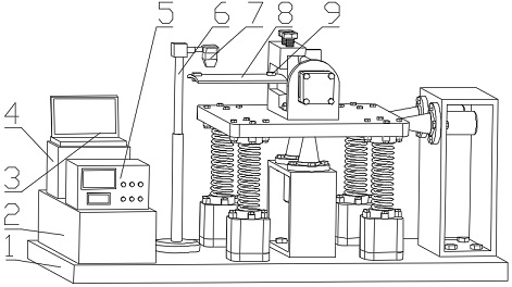
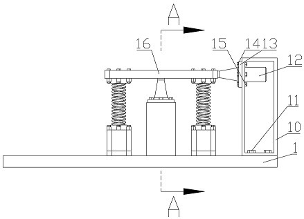
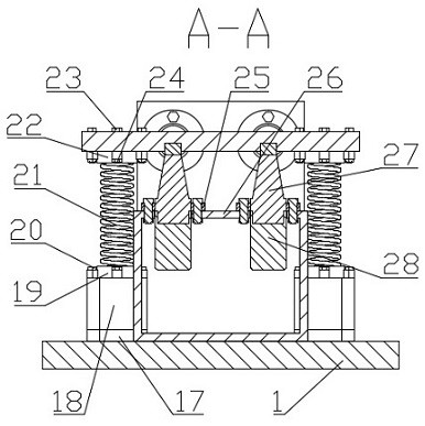
[0020] The present invention is a high-frequency vibration fatigue test device for thin-walled blade parts, which mainly includes a signal processing and control device, an ultrasonic vibration device, a special fixture device for blades, and the like. Refer to the following examples Figures 1~5 .

[0021] like figure 1 As shown, it is a schematic diagram of the structure of the device of the present i...


PUM


Abstract

The invention discloses a high-frequency vibration fatigue test device for thin-wall blade parts. The high-frequency vibration fatigue test device comprises a signal processing and control device, an ultrasonic vibration device, a special blade clamp device and the like. Wherein the ultrasonic vibration device mainly comprises a vibration table, springs, a base and an ultrasonic vibration mechanism, the ultrasonic vibration mechanism is composed of a flange plate, an ultrasonic transducer and an ultrasonic amplitude-change pole, and in the ultrasonic vibration device, a plurality of springs are designed to assist in supporting the vibration table, so that the stress of the ultrasonic vibration mechanism is reduced; and then the ultrasonic generator provides ultrasonic frequency electric energy for the ultrasonic vibration mechanism, so that the ultrasonic vibration mechanism applies high-frequency vibration in two directions to the vibration table, and high-frequency vibration of the ultrasonic vibration device is realized. The pressure sensor is arranged in the special clamp device for the blade, so that the clamping force of the tenon part of the blade is monitored in real time, the clamping force of the blade in a vibration fatigue test is always in a stable area, the stress state of the tenon root is monitored in real time, and the clamping stability of vibration fatigue of the blade is improved.

Description

technical field [0001] The patent of the present invention relates to a high-frequency vibration fatigue test device for thin-walled blade parts, which belongs to the technical field of vibration fatigue test. Background technique [0002] Thin-walled blade parts are one of the key and important parts in aero-engines. Such parts are usually in high temperature, high pressure and high-speed working environments, and are the main failure-prone parts of aero-engines. During the working process, the aero-engine blades are subjected to complex airflow impact, which causes the blades to vibrate. When the vibration impact force exceeds the fatigue limit of the blade, fatigue cracks will appear in the blade, which will gradually develop into fatigue fractures, resulting in failure of the engine during operation, and may even cause serious accidents. Therefore, in the development stage of aero-engine blades, it is necessary to conduct vibration fatigue tests on blades to determine t...

Claims


Application Information

Patent Timeline
Patent Type & Authority Applications(China)
IPC IPC(8): G01M7/02B25B11/00
CPCG01M7/02B25B11/00Y02E10/72
Inventor 马俊金李浩明焦锋赵波高国富向道辉崔晓斌庞晓艳
Owner HENAN POLYTECHNIC UNIV
Learn More