
Generator and wind generating set

A generator and radial air duct technology, applied in wind turbine combinations, wind turbines, engines, etc., can solve the problems of low integration, insulation breakdown, large space occupation, etc., to improve safety performance and integration. Tall, small footprint effect

Pending Publication Date: 2022-06-24
XINJIANG GOLDWIND SCI & TECH
View PDF0 Cites 0 Cited by
  • Summary
  • Abstract
  • Description
  • Claims
  • Application Information

AI Technical Summary

Problems solved by technology

[0002] The loss generated by the generator when the wind turbine is running will cause the temperature rise of its components. Excessive temperature will affect the life of the wind turbine and even cause the wind turbine to fail to operate normally.
For example, long-term high-temperature operation of the generator will reduce the insulation life of the generator, and even cause adverse phenomena such as insulation breakdown. There is a permanent drop in power, so cooling design is very important in generators
[0003] In the existing wind turbines, the generators often adopt air-to-air heat exchange system cooling mode, and the cooling structure of the generator is usually arranged in the nacelle of the wind turbine, and special ventilation pipelines are needed to connect the components to be dissipated and the heat exchange system of the generator. connection, takes up a lot of space, and has a low degree of integration

Method used


Image

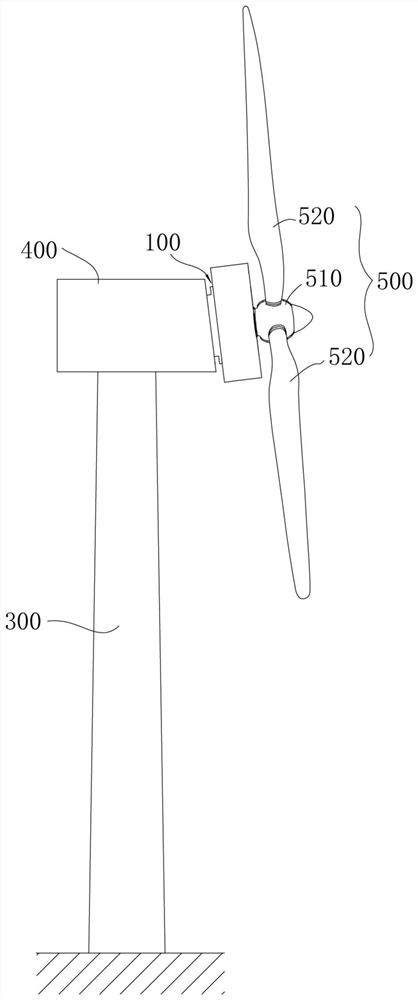
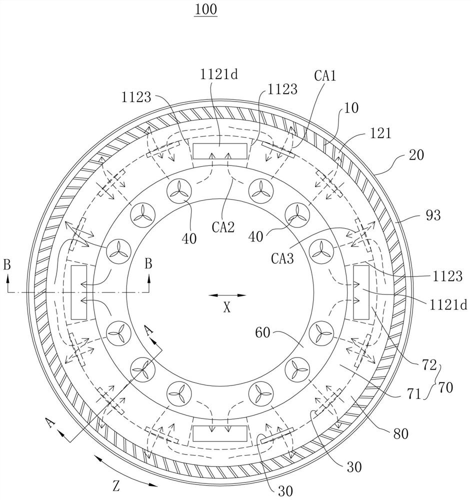
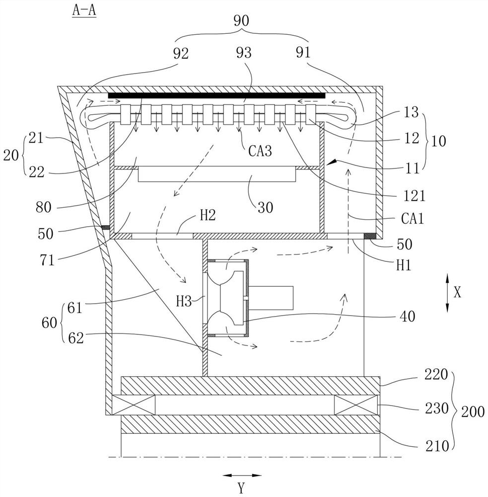
  • Generator and wind generating set
  • Generator and wind generating set
  • Generator and wind generating set

Examples


Embodiment Construction

[0042] Features and exemplary embodiments of various aspects of the invention are described in detail below. In the following detailed description, numerous specific details are set forth in order to provide a thorough understanding of the present invention. However, it will be apparent to one skilled in the art that the present invention may be practiced without some of these specific details. The following description of the embodiments is only intended to provide a better understanding of the present invention by illustrating examples of the invention. In the drawings and the following description, at least some well-known structures and techniques are not shown in order to avoid unnecessarily obscuring the present invention; and, the dimensions of some structures may be exaggerated for clarity. Furthermore, the features, structures or characteristics described below may be combined in any suitable manner in one or more embodiments.

[0043] The orientation words appearin...


PUM


Abstract

The generator comprises a stator, the stator comprises a stator support and a stator iron core which are sequentially arranged in the radial direction of the stator, a radial air channel is formed in the stator iron core, and the stator support is used for being connected with a shafting structure and forming an inner cavity; the inner cavity comprises a first cavity, a second cavity and a third cavity which are sequentially arranged in the radial direction, and the third cavity communicates with the radial air channel. The rotor is arranged around the shafting structure, a circulating chamber is formed between the rotor and the stator, and the circulating chamber is communicated with the first chamber and the radial air duct; the heat exchanger is arranged in at least one of the second cavity and the third cavity and communicates with the second cavity and the third cavity; and the fan is arranged in the first cavity so as to drive airflow to circularly flow in the first cavity, the circulating cavity, the third cavity, the heat exchanger and the second cavity. According to the generator and the wind generating set provided by the embodiment of the invention, the generator integrates a cooling function and is compact in structure, small in occupied space and high in integration degree.

Description

technical field [0001] The present invention relates to the technical field of wind power, in particular to a generator and a wind power generator set. Background technique [0002] When the wind turbine is running, the loss generated by the generator will cause the temperature of its components to rise. Excessive temperature will affect the life of the wind turbine and even cause the wind turbine to fail to operate normally. For example, the long-term high temperature operation of the generator will reduce the insulation life of the generator, and even cause undesirable phenomena such as insulation breakdown. If the generator is a permanent magnet motor, the magnetism of the permanent magnet will decay in a high temperature environment, resulting in demagnetization. Power drops permanently, therefore, cooling design is very important in generators. [0003] In the existing wind turbine generator set, the generator often adopts the air-air heat exchange system cooling metho...

Claims


Application Information

Patent Timeline
IPC IPC(8): H02K9/08H02K3/24F03D9/25F03D15/20
CPCH02K9/08H02K3/24F03D9/25F03D15/20Y02E10/72
Inventor 刘军卫王丁会方涛
Owner XINJIANG GOLDWIND SCI & TECH
Learn More