
Vertical stirring and conveying structure

A vertical stirring and stirring paddle technology is applied in the field of vertical stirring and conveying structures, which can solve the problems of high manufacturing cost, maintenance cost, inconvenient cleaning, etc., and achieve the effect of improving operation capacity, facilitating transportation, and reducing the arrangement of vertical stirring motors.

Pending Publication Date: 2022-06-28
WUXI LINGOOD MACHINERY TECH
View PDF0 Cites 0 Cited by
  • Summary
  • Abstract
  • Description
  • Claims
  • Application Information

AI Technical Summary

Problems solved by technology

[0003] In order to overcome the hardening of materials, two sets of independent agitators are usually used at present, or ball-type buckets are used, but the disadvantages are obvious. If it is necessary to add stirring paddles and electric motors for driving the paddles on the top hopper cover, clean the materials above them. It is necessary to ensure the space for pulling up the stirring paddle, and the hopper cover with the stirring motor and paddle fixed must be pulled up, which is inconvenient for cleaning, resulting in high manufacturing cost and maintenance cost, so the traditional design idea needs to be improved

Method used


Image

  • Vertical stirring and conveying structure
  • Vertical stirring and conveying structure
  • Vertical stirring and conveying structure

Examples


Embodiment Construction

[0023] The technical solutions in the embodiments of the present invention will be clearly and completely described below with reference to the accompanying drawings in the embodiments of the present invention. Obviously, the described embodiments are only a part of the embodiments of the present invention, but not all of the embodiments. Based on the embodiments of the present invention, all other embodiments obtained by those of ordinary skill in the art without creative efforts shall fall within the protection scope of the present invention.

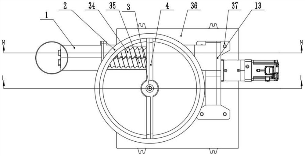
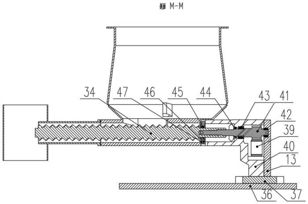
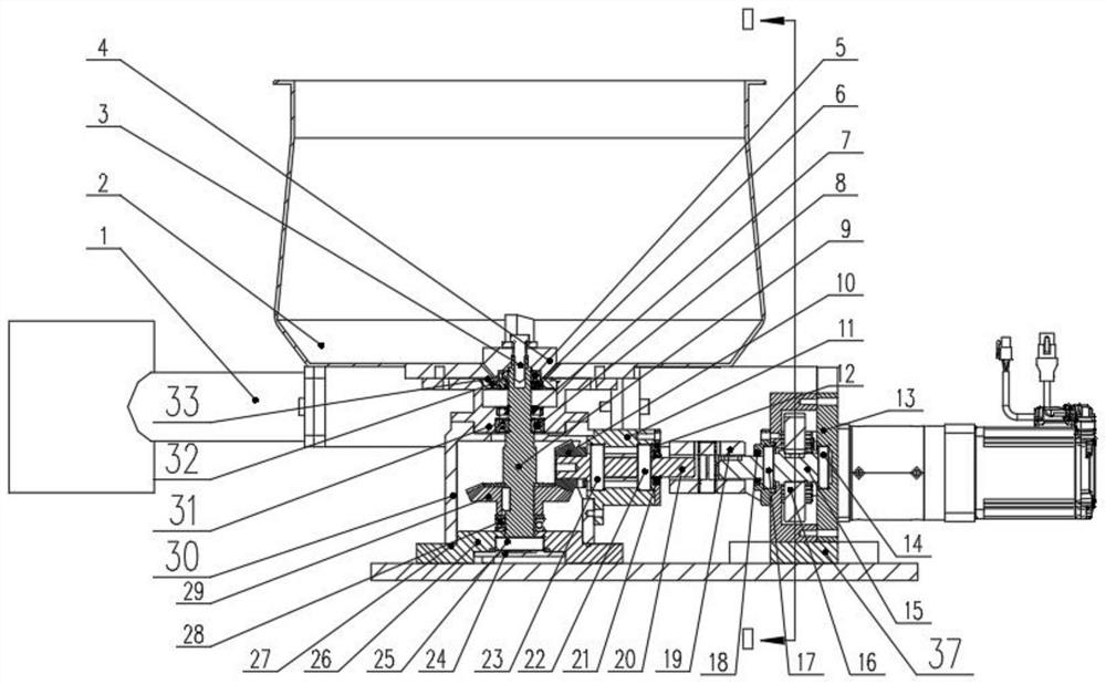
[0024] refer to Figure 1 to Figure 4 , a vertical stirring and conveying structure, including a frame and a conical bucket 2, the bottom of the conical bucket 2 is communicated with a discharge port 1, and a stirring paddle 4 is rotatably connected at the inner bottom of the conical bucket 2, and the stirring The paddle 4 is fixed to the outside of the vertical stirring shaft 9 through the stirring paddle bolt 3, and the vertical sti...


PUM


Abstract

According to the technical scheme, the vertical stirring and conveying structure is characterized in that the vertical stirring and conveying structure comprises a rack and a conical hopper, the bottom of the conical hopper communicates with a discharging opening, a stirring paddle is rotationally connected to the bottom of the interior of the conical hopper, and the stirring paddle is fixed to the outer portion of a vertical stirring shaft through a stirring paddle bolt; the vertical stirring shaft is in sealed connection with the conical hopper through a first sealing structure, and a first transition shaft is rotationally connected into the first angular contact ball bearing and the second angular contact ball bearing; according to the vertical stirring and conveying structure, the power assembly is adopted to drive the first self-cleaning screw on the first output shaft to rotate, drive the second self-cleaning screw fixed outside the second output shaft to rotate, and drive the second transition shaft and the first transition shaft to rotate, so that the operation capability is improved, the investment is reduced, and the injection of materials in the conical hopper is facilitated; and a bridging phenomenon is not easy to occur.

Description

technical field [0001] The invention relates to the field of conveying devices, in particular to a vertical stirring conveying structure. Background technique [0002] In some common screw conveyors, since the shape of the hopper is usually a cone with a large upper and a small lower, the wall surface has a slope, and the cross-sectional area becomes smaller as it goes downward, so it is suitable for powders with high compressibility and adhesion. In other words, the bridging phenomenon in which the powder or granule does not fall locally or as a whole, or the rat-hole phenomenon in which only the material in the middle part falls is likely to occur. Because the hopper is connected and fixed on the horizontal screw conveying pipeline, when the feeding screw in the screw conveying pipeline advances, the material in the hopper tends to accumulate at the bottom, and due to the shape limitation of the hopper, the gap between the hopper and the screw conveying pipeline is caused....

Claims


Application Information

Patent Timeline
IPC IPC(8): B65D88/68B65D90/00B65D90/54
CPCB65D88/68B65D90/00B65D90/54
Inventor 吴贞号刘德宁王成浩郑伟峰耿莉
Owner WUXI LINGOOD MACHINERY TECH
Learn More