
Chip mounting device

A chip mounting, No. 1 technology, applied in the direction of semiconductor devices, electrical components, circuits, etc., can solve problems such as solder joints not corresponding, affecting chip mounting accuracy, etc., to reduce the length of the route, facilitate welding operations, and shorten the distance Effect

Active Publication Date: 2022-06-28
山东睿芯半导体科技有限公司
View PDF12 Cites 5 Cited by
  • Summary
  • Abstract
  • Description
  • Claims
  • Application Information

AI Technical Summary

Problems solved by technology

[0002] Wafer / chip in electronics is a way to miniaturize circuits (mainly including semiconductor devices, including passive components, etc.), and is often manufactured on the surface of semiconductor wafers. Chips are usually a general term for semiconductor component products. Under the existing technology, chips are generally fixedly mounted on the circuit substrate by welding. The technical term is chip placement. The traditional placement device has a link of picking up chips and transporting them. Usually, mechanical adsorption hands are used to pick up chips and then re-attach them. Placed on the solder joints of the substrate, but often during the transportation process of the mechanical adsorption hand, the chip will be shifted during transportation due to the complicated transportation route of the mechanical adsorption hand, which will eventually cause the soldering to correspond to the solder joints on the substrate. If not, it will affect the accuracy of chip mounting, so it is necessary to provide a chip mounting device to solve the above problems

Method used


Image

  • Chip mounting device
  • Chip mounting device
  • Chip mounting device

Examples


Embodiment Construction

[0037] In order to further understand the features, technical means, and specific goals and functions of the present invention, the present invention will be described in further detail below with reference to the accompanying drawings and specific embodiments.

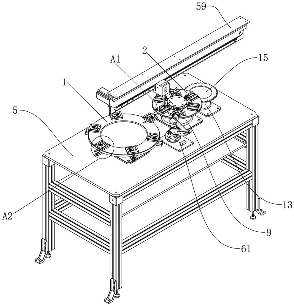
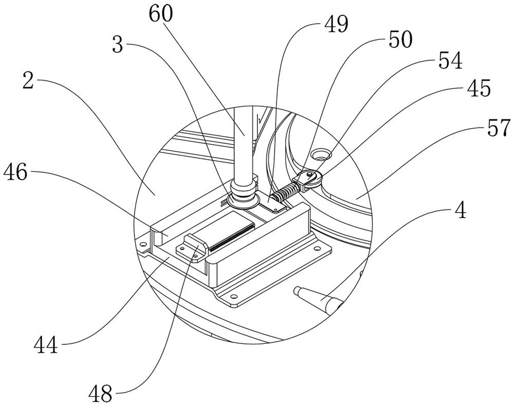
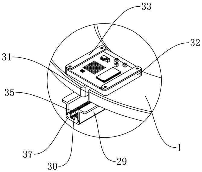
[0038] refer to Figure 1 to Figure 23 The shown chip mounting device includes a horizontal transfer assembly, a soldering assembly and a double turntable assembly, the double turntable assembly includes two No. Tray 2, the No. 1 carrier tray 1 and No. 2 carrier tray 2 are distributed at intervals along the horizontal direction and the centers of the two are on the same horizontal line, and the No. 1 carrier tray 1 is provided with several for fixing the substrate and can follow the No. 1 tray The No. 1 clamp that the carrier plate 1 rotates together, several of the No. 1 clamps are evenly distributed along the circumferential direction of the No. 1 carrier plate 1, and the angle between each pair of the adjacent No. ...


PUM


Abstract

The invention relates to the technical field of semiconductor device manufacturing, in particular to a chip mounting device which comprises a horizontal transferring assembly, a welding assembly and a double-rotating-disc assembly, the double-rotating-disc assembly comprises a first carrying disc and a second carrying disc, the first carrying disc is provided with a plurality of first clamps, the second carrying disc is provided with a plurality of second clamps, and the first clamps and the second clamps are arranged on the horizontal transferring assembly. The horizontal displacement assembly comprises a suction cup, the welding assembly comprises a welding gun, a segmentation driving assembly is arranged below the double-rotary-disc assembly, the double-rotary-disc assembly of the device is used for carrying a substrate and a chip, a first carrying disc and a second carrying disc in the double-rotary-disc assembly can synchronously rotate in opposite directions, the rotating angles of the two carrying discs each time are consistent, and therefore the substrate and the chip can be separated from each other. The welding position of the substrate and the welding position of the chip are ensured to be always on the same horizontal line, so that the conveying route length of the chip picked up by the suction cup is reduced, only short-distance horizontal displacement is needed, the chip is prevented from deviating in the conveying process, and the welding precision is ensured.

Description

technical field [0001] The present invention relates to the technical field of manufacture of semiconductor devices, in particular to a chip mounting device. Background technique [0002] Chip / chip in electronics is a way to miniaturize circuits (mainly including semiconductor equipment, but also passive components, etc.), and is often fabricated on the surface of semiconductor wafers. Chip is usually a general term for semiconductor component products. In the existing technology, the chip is generally fixed and mounted on the circuit substrate by welding. The technical term is the chip mounting. The traditional mounting device has a link for picking up the chip and transporting it, usually using a mechanical suction hand to pick up the chip and then. It is placed on the solder joints of the substrate, but often during the transportation of the mechanical adsorption hand, due to the complex transportation route of the mechanical adsorption hand, the chip will be offset durin...

Claims


Application Information

Patent Timeline
Patent Type & Authority Applications(China)
IPC IPC(8): H01L21/683H01L21/60
CPCH01L21/6838H01L24/75H01L2224/758
Inventor 郭军王汉波
Owner 山东睿芯半导体科技有限公司
Learn More