
Ultra-wideband antenna

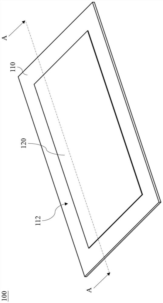
An ultra-wideband antenna and patch technology, applied in the field of antennas, can solve the problems of poor positioning performance, complex shape, unstable processing, etc., and achieve the effect of improving coupling, broadening bandwidth, and achieving impedance matching.

Pending Publication Date: 2022-06-28
KUNSHAN LIANTAO ELECTRONICS CO LTD
View PDF0 Cites 2 Cited by
  • Summary
  • Abstract
  • Description
  • Claims
  • Application Information

AI Technical Summary

Problems solved by technology

[0004] The embodiment of the present application provides an ultra-wideband antenna, which can solve the problem of poor positioning performance and poor positioning performance in the prior art where a single patch antenna is used to increase the standing wave ratio bandwidth of the antenna by changing the feeder line or changing the shape of the patch. The complex shape leads to the problem of processing instability

Method used


Image

  • Ultra-wideband antenna
  • Ultra-wideband antenna
  • Ultra-wideband antenna

Examples


Embodiment Construction

[0024] The embodiments of the present invention will be described below with reference to the related drawings. In the figures, the same reference numbers refer to the same or similar components or method flows.

[0025] It must be understood that words such as "comprising" and "comprising" used in this specification are used to indicate the existence of specific technical features, values, method steps, job processes and / or components, but do not exclude the possibility of adding Further technical features, values, method steps, job processes, components, or any combination of the above.

[0026] It must be understood that when an element is described as being "connected" or "coupled" to another element, it can be directly connected or coupled to the other element, and intervening elements may be present. In contrast, when a component is described as being "directly connected" or "directly coupled" to another component, there are no intervening components present.

[0027] ...


PUM


Abstract

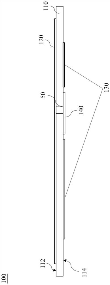
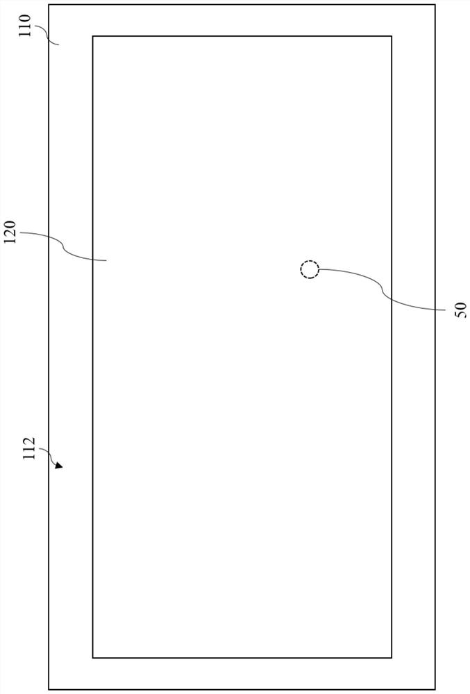
The invention discloses an ultra wide band antenna. The ultra-wideband antenna is arranged on a communication device comprising a metal component, and the ultra-wideband antenna comprises a first dielectric substrate, a main radiation patch, a parasitic radiation patch and an impedance matching patch, the first dielectric substrate is provided with a first conductive via hole; the main radiation patch is arranged on the upper surface of the first dielectric substrate and is electrically connected with the first conductive via hole; the parasitic radiation patch is arranged on the lower surface of the first dielectric substrate; the impedance matching patch and the parasitic radiation patch are located on the same plane and electrically connected with the first conductive via hole, the parasitic radiation patch surrounds the impedance matching patch and is isolated from the impedance matching patch, and the impedance matching patch is provided with a feeding point. Wherein the parasitic radiation patch is configured to couple energy from the main radiation patch, and the parasitic radiation patch is configured to generate a notch frequency close to a notch frequency generated by the main radiation patch so as to broaden a frequency band bandwidth.

Description

technical field [0001] The present application relates to the field of antenna technology, and in particular, to an ultra-wideband antenna. Background technique [0002] Ultra Wide Band (UWB) is a wireless carrier communication technology, which is mainly used in short-distance high-speed data communication of about 10 meters. It uses nanosecond to microsecond non-sine wave narrow pulses to transmit data. Very low power signals are transmitted over a wide frequency spectrum. [0003] At present, UWB antennas mostly adopt a single-radiation patch design (ie, a single-patch antenna), wherein the radiation patch is located above the dielectric substrate, and the antenna reference ground is located on the bottom surface of the dielectric substrate. However, the single patch antenna has the problem of narrow bandwidth due to its limited physical properties. Therefore, the relevant industry proposes to increase the VSWR bandwidth of the antenna by changing the shape of the taper...

Claims


Application Information

Patent Timeline
IPC IPC(8): H01Q1/38H01Q1/50H01Q5/50
CPCH01Q1/38H01Q1/50H01Q5/50
Inventor 何坤林付荣王俊张龙
Owner KUNSHAN LIANTAO ELECTRONICS CO LTD
Learn More