Broadband lens for generating deflection Bessel multi-beam and regulation and control method

A Bessel multi-lens technology, applied in the field of communication, to achieve the effect of widening bandwidth, improving transmittance, and overcoming processing difficulties

Pending Publication Date: 2022-05-10
SOUTH CHINA UNIV OF TECH
View PDF0 Cites 2 Cited by
  • Summary
  • Abstract
  • Description
  • Claims
  • Application Information

AI Technical Summary

Problems solved by technology

Bessel beams can be used for wireless energy transmission. In order to achieve efficient energy use and flexibility, it is necessary to allocate energy to Bessel multi-beams. There are few studies on this in the existing literature.

Method used


Image

  • Broadband lens for generating deflection Bessel multi-beam and regulation and control method
  • Broadband lens for generating deflection Bessel multi-beam and regulation and control method
  • Broadband lens for generating deflection Bessel multi-beam and regulation and control method

Examples


Embodiment 1

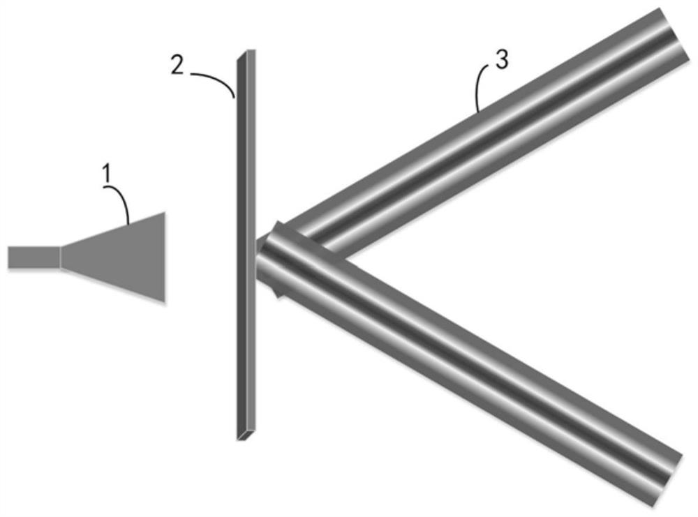
[0039] Such as Figure 1-Figure 2 As shown, a broadband lens for generating deflected Bessel multi-beams includes a feed source 1 and N metasurface units 2, and the N metasurface units can be arranged in a circular or rectangular array. The feed generates spherical waves to irradiate the metasurface unit, and forms multiple Bessel beams on one side of the metasurface unit. In this embodiment, the feed source 1 is located at a certain distance to the left of the metasurface unit 2, and generates spherical waves to irradiate the metasurface and form multiple Bessel beams 3 on the right side of the metasurface.

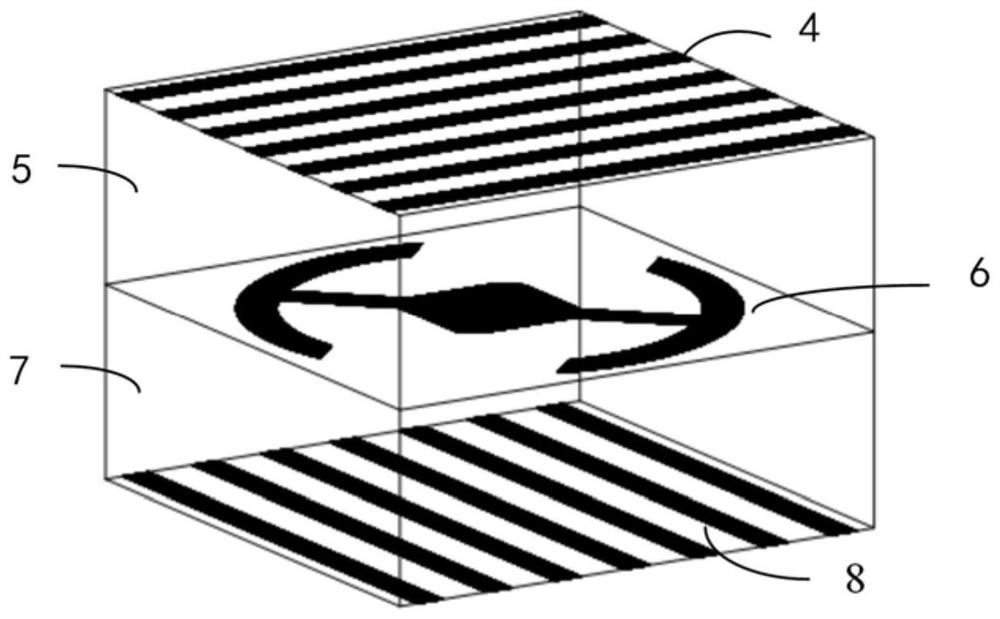
[0040] Further, the metasurface unit includes a first polarization grid 4, a first dielectric plate 5, a polarization conversion surface 6, a second dielectric plate 7, and a second polarization grid 8 stacked in order from top to bottom. The polarization conversion surface is mirror-symmetrical along the y-axis to achieve a phase difference of 180 degrees. The 180-degr...

Embodiment 2

[0065] The difference between this embodiment and Embodiment 1 is that the compensation phase required by the radiation unit is different, such as Figure 8(a) ~ Figure 8(c) As shown, the present embodiment 2 is used to generate θ=30°, with θ=-30°, Bessel beams of equal intensity, see Figure 9(a) ~ Figure 9(e) .

Embodiment 3

[0067] The difference between this embodiment and Embodiment 1 is that the compensation phase required by the radiation unit is different, such as Figure 10(a) ~ Figure 10(c) shown for generating θ=30°, with θ=-30°, Bessel beams with unequal intensity distribution. Set the amplitude distribution ratio of the Bessel beam at 14GHz to 1:0.8, use the genetic algorithm to optimize the phase weighting, and obtain the optimized phase superimposing the spherical wave to the phase that needs to be compensated by the plane wave, and obtain the phase as shown in Figure 10(a) . refer to Figure 11(a) ~ Figure 11(e) , Bessel beams with unequal power distribution are obtained from 10GHz to 18GHz, and the amplitude distribution ratio is 1:0.8 at 14GHz.

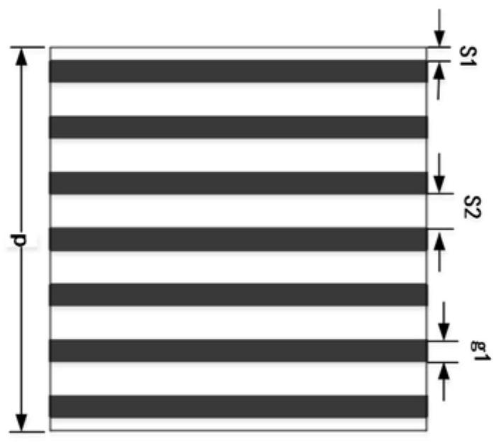
[0068] The metasurface unit of the present invention is composed of N radiation units arranged in an array, and the unit includes three layers of metal and two layers of dielectric substrates, wherein the upper and lower layers of met...


PUM

PropertyMeasurementUnit
Length and widthaaaaaaaaaa
Heightaaaaaaaaaa

Abstract

The invention discloses a broadband lens capable of generating deflection Bessel multi-beams and a regulation and control method, the broadband lens comprises a feed source and N metasurface units, the feed source generates spherical waves to irradiate the metasurface units, a plurality of Bessel beams are formed on one sides of the metasurface units, the metasurface units are adjustable in phase, and N is a positive integer greater than or equal to 1. The polarization metasurface comprises a first polarization grid, a first dielectric plate, a polarization conversion surface, a second dielectric plate and a second polarization grid which are sequentially stacked, the polarization conversion surface is in mirror symmetry along the y axis, 180-degree phase difference is achieved, 180-degree phase transformation is obtained through size transformation of the polarization metasurface, and 360-degree transmission phase change is further obtained. The transmission type Bessel beam antenna provided by the invention has the characteristics of planarization, broadband, multiple beams and adjustable beam energy.

Description

technical field [0001] The invention relates to the communication field, in particular to a broadband lens for generating deflected Bessel multi-beams and a control method. Background technique [0002] Since the Bessel beam was proposed by Durnin in 1987, it has received extensive attention due to its non-diffraction property. It can concentrate the energy of electromagnetic waves in a certain direction and keep the energy constant at a certain distance when propagating in free space. It has the potential to be applied to high-speed communication, wireless energy transmission, and laser micromachining. [0003] In the field of microwave and millimeter waves, there are two common methods for generating Bessel beams. One is to design an antenna whose aperture field is similar to a Bessel function, such as a waveguide leaky wave antenna or a radial slot array, but it is difficult to form a good Bessel function distribution characteristic of the electric field on the aperture ...

Claims


Application Information

Patent Timeline
IPC IPC(8): H01Q15/00H01Q1/38H01Q19/12H01Q19/13H01Q19/15H01Q15/12
CPCH01Q15/004H01Q1/38H01Q19/12H01Q19/132H01Q19/15H01Q15/12
Inventor 黄惠芬汤秀铃
Owner SOUTH CHINA UNIV OF TECH
Why Eureka
Try Eureka