
Low-frequency dipole transmitting transducer

A technology for transmitting transducers and dipoles, which is used in surveying, wellbore/well components, earth-moving drilling, etc. To achieve high-power transmission and other issues, to achieve the effect of broadening the bandwidth and facilitating high-power design

Inactive Publication Date: 2012-10-24
INST OF ACOUSTICS CHINESE ACAD OF SCI
View PDF5 Cites 4 Cited by
  • Summary
  • Abstract
  • Description
  • Claims
  • Application Information

AI Technical Summary

Problems solved by technology

However, the above transducers all have deficiencies: usually only two pieces of ceramics are used in the triple stack and the 1-3 working mode of the material is used when working, and a large voltage will be generated on the bonding surface when a large voltage is applied. The shear stress is easy to damage the device. These deficiencies lead to the inability of the transducer to achieve high-power emission; the moving coil structure can achieve a low frequency and flat response curve, but this structure inherently has the problem of low radiation efficiency and also High-power transmission cannot be achieved; the fundamental resonance frequency of the mosaic ring is related to the diameter of the ring, and reducing the design frequency of the transducer requires increasing the diameter of the transducer
Now the aperture of the wellbore has brought real difficulties to the low frequency of this type of structure transducer

Method used


Image

  • Low-frequency dipole transmitting transducer

Examples


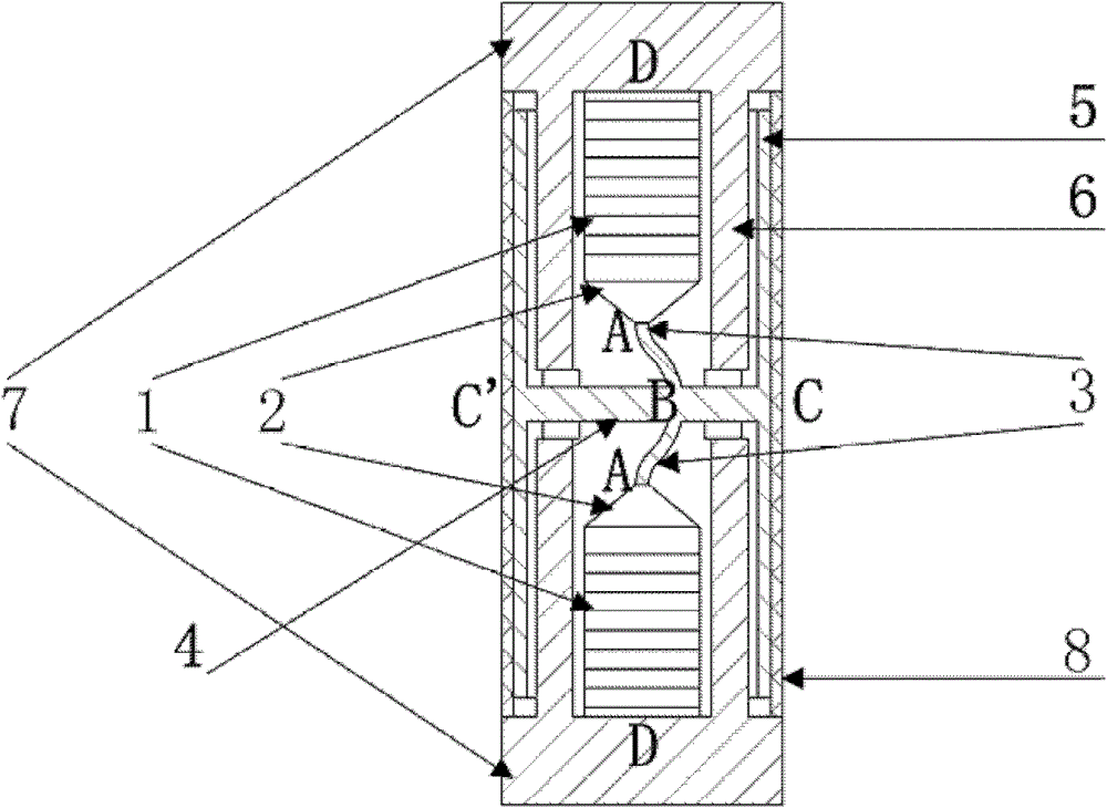
Embodiment Construction

[0026] Next, the present invention will be further described according to the accompanying drawings

[0027] The transducer consists of two sets of ceramic stacks 1, transition rods 2, curved beams 3, transition beams 4, swing columns 5, rigid beams 6, end cover plates 7 and watertight layers 8. The overall length of the transducer in the embodiment is 193mm. Among them, the ceramic stack 1 is made of PZT-4 piezoelectric ceramics; the transition rod 2, the bending beam 3, the transition beam 4, and the swing column 5 are all made of TC4 titanium alloy; the rigid beam 6 and the end cover plate 7 are made of 45# steel, watertight Layer 8 adopts JA-2S polyurethane rubber.

[0028] The ceramic stack 1 is divided into two groups, and each group of ceramic stacks is mechanically bonded in series by eight φ30mm×5mm polarized ceramic sheets and one φ30mm×2mm non-polarized ceramic sheet. The direction of the electrodes of the sheet ceramics is opposite, and the unpolarized ceramic sh...


PUM

PropertyMeasurementUnit
Modulusaaaaaaaaaa

Abstract

The invention relates to a low-frequency dipole transmitting transducer. The transducer comprises a basic oscillator, a transition rod (2), a bent beam (3), a transition beam (4), a swing column (5), a rigid beam (6), end cover plates (7) and a water-tight layer (8), wherein the basic oscillator is arranged in the rigid beam (6) and is formed by serially connecting upper and lower ceramic piles (1) with the bent beam (3)through the transition rod (2); the basic oscillator is clamped through the rigid beam (6) and the end cover plates (7) arranged at the two ends of the rigid beam (6); the swing column (5) and the water-tight layer (8) are sequentially sleeved outside the rigid beam (6); the transition beam (4) is arranged in a hole of the side wall in the middle of the rigid beam (6); and the middle parts of the bent beam (3) and the swing column (5) are connected through the transition beam (4). The low-frequency dipole transmitting transducer disclosed by the invention has the advantages that a piling direction of an excitation source is a vertical direction so that a low-frequency large-power design of the transducer is conveniently realized and the bandwidth of the transducer can be better expanded.

Description

technical field [0001] The invention relates to the field of acoustic detection, in particular, the invention relates to a low-frequency dipole emitting transducer. Background technique [0002] Petroleum is known as the blood of industry. Now petroleum and its chemical products have been integrated into every corner of our production and life. However, as a non-renewable resource, it has been depleted after more than 100 years of exploitation, and the remaining reserves are difficult to exploit and exploit. The cost is getting higher and higher, and oil extraction has entered the era of fine mining. [0003] Sound waves can effectively propagate over long distances in solid, liquid, and gas three-phase media. By measuring acoustic parameters such as sound attenuation and sound velocity to estimate formation properties such as porosity, permeability, and water saturation, acoustic logging has become a very important measurement method in petroleum exploration and other fiel...

Claims


Application Information

Patent Timeline
IPC IPC(8): E21B47/14B06B1/06G01V1/40
Inventor 莫喜平戴郁郁
Owner INST OF ACOUSTICS CHINESE ACAD OF SCI
Learn More