Combined self-expanding inferior vena cava stent

A vena cava and self-expanding technology, applied in the direction of the stent, can solve problems such as shedding, atrial wall puncture, arrhythmia, etc., and achieve the effect of stent support and stability, strengthening the support effect, and fitting the anatomical structure

Inactive Publication Date: 2022-07-01
河南省直第三人民医院
View PDF0 Cites 0 Cited by
  • Summary
  • Abstract
  • Description
  • Claims
  • Application Information

AI Technical Summary

Problems solved by technology

[0004] However, due to the thin wall of the right atrium of the heart, according to the direction of blood flow, the right atrium has three entrances and one exit, the entrance is the ostium of the superior and inferior vena cava and the ostium of the coronary sinus, and the exit is the opening of the right atrium. The right atrium leads to the right ventricle, The existing inferior vena cava stent

Method used


Image

  • Combined self-expanding inferior vena cava stent
  • Combined self-expanding inferior vena cava stent
  • Combined self-expanding inferior vena cava stent

Examples


Embodiment 1

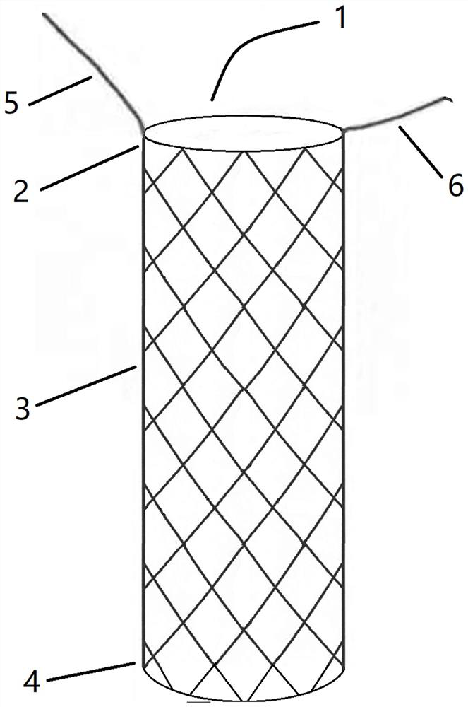
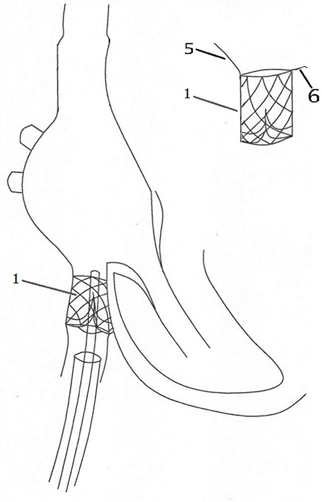
[0023] like Figure 1-Figure 3 As shown, the combined self-expanding inferior vena cava stent of the present invention is composed of the upper end 2 of the stent, the middle part of the stent 3, the lower end 4 of the stent and the support body of the stent. Main body 1, the bracket main body 1 is an integral structure, the height of the upper end 2 of the bracket forming the bracket main body 1 gradually decreases from left to right, and the height is smoothly transitioned by repeated winding and weaving, and the right side of the upper end 2 of the bracket is The distance between the vertical projection point of the vertex to the left side of the stent body 1 and the left vertex of the stent body 1 is 0.5-3.0mm. The distance should not be set too large to avoid unnecessary formation between the stent body 1 and the inferior vena cava tissue wall. If the gap is too large, the stability of the stent and the formation of thrombus will be affected, and the implantation effect o...

Embodiment 2

[0032] The structure of this embodiment is basically the same as that of Embodiment 1, the difference is that in this embodiment, as figure 2 As shown, the lower end 4 of the bracket that forms the bracket body 1 gradually becomes thinner from top to bottom (it can be made by forging or grinding with a cylindrical wire of the same diameter), and the end of the lowermost end is the thinnest and has an obliquely upward Flat barbs to ensure smooth blood flow and positioning and anchoring of the stent.

[0033] In this embodiment, the right vertex and the left vertex of the upper end 2 of the support are arranged in parallel, and the position of the first development is substantially parallel to the position of the third.


PUM

PropertyMeasurementUnit
Lengthaaaaaaaaaa
The inside diameter ofaaaaaaaaaa
Lengthaaaaaaaaaa

Abstract

The inferior vena cava stent is formed by combining a stent upper end, a stent middle section, a stent lower end and stent supporting bodies, the stent supporting bodies comprise the left stent supporting body and the right stent supporting body which are different in height, and the stent supporting bodies have certain elasticity so that the stent supporting bodies can be fixed to the right atrium inner wall and the atrioventricular opening tissue wall; but the elasticity is not too large to prevent the atrial wall from being punctured; the stent middle section is provided with an inner surface and an outer surface which are different in finish degree, and in the implanting process of the inferior vena cava stent, the implanting position can be adjusted in real time and released accurately through matching of developing marks, so that the stent is more attached to the anatomical structure of the inferior vena cava of the human body; due to the special shape design of the left stent supporting body and the right stent supporting body, the stent is more attached to the inner wall of a right atrium and the tissue wall of an atrioventricular opening, the supporting effect of the stent is further enhanced through the frosted rough outer surface of the middle section of the stent and the flat barbs at the lower end of the stent, and implantation is safer and more reliable.

Description

technical field [0001] The invention relates to the field of implantable medical devices, in particular to a combined self-expanding inferior vena cava stent. Background technique [0002] The inferior vena cava is the largest vein in the human body. The normal inner diameter of the inferior vena cava is 2 cm in the proximal segment, 1.9-2.1 cm in the interrupted segment, and 1.7-1.9 cm in the distal segment. It is the main trunk of the inferior vena cava system. It is at the level of the fifth lumbar vertebra , a few in the fourth lumbar vertebra, formed by the confluence of the left and right common iliac veins, the inferior vena cava is located in the right front of the spine, ascends along the right side of the abdominal aorta, passes through the posterior vena cava groove of the liver, and enters the vena cava through the diaphragm. The thoracic cavity, which enters and opens into the right atrium, collects venous blood from the lower extremities, pelvis, and abdominal ...

Claims


Application Information

Patent Timeline
IPC IPC(8): A61F2/82A61F2/848
CPCA61F2/82A61F2/848A61F2002/8483A61F2250/0098
Inventor 彭喜涛袁启东梁冰王海生侯竞远刘俊华
Owner 河南省直第三人民医院
Why Eureka
Try Eureka