Stirring system and stirring method of stirring station

A mixing system and mixing station technology, applied in mixing plants, cement mixing devices, chemical instruments and methods, etc., can solve problems such as harsh environments

Pending Publication Date: 2022-07-01
重庆国浩永固新型建材有限公司
View PDF0 Cites 0 Cited by
  • Summary
  • Abstract
  • Description
  • Claims
  • Application Information

AI Technical Summary

Problems solved by technology

[0002] The mixing station is mainly engaged in commercial concrete, using cement, fly ash, sand and stone, water reducing agent and other materials to mix and mix in strict accordance with the ratio of national standards, and transport it to the building by mixer truck (commonly known as "snail truck") On th

Method used


Image

  • Stirring system and stirring method of stirring station

Examples


Example Embodiment

[0013] In order to make the technical means realized by the present invention, the creation features, the achievement of the purpose and the effect clearer and easier to understand, the present invention will be further elaborated below in conjunction with the accompanying drawings and specific embodiments:

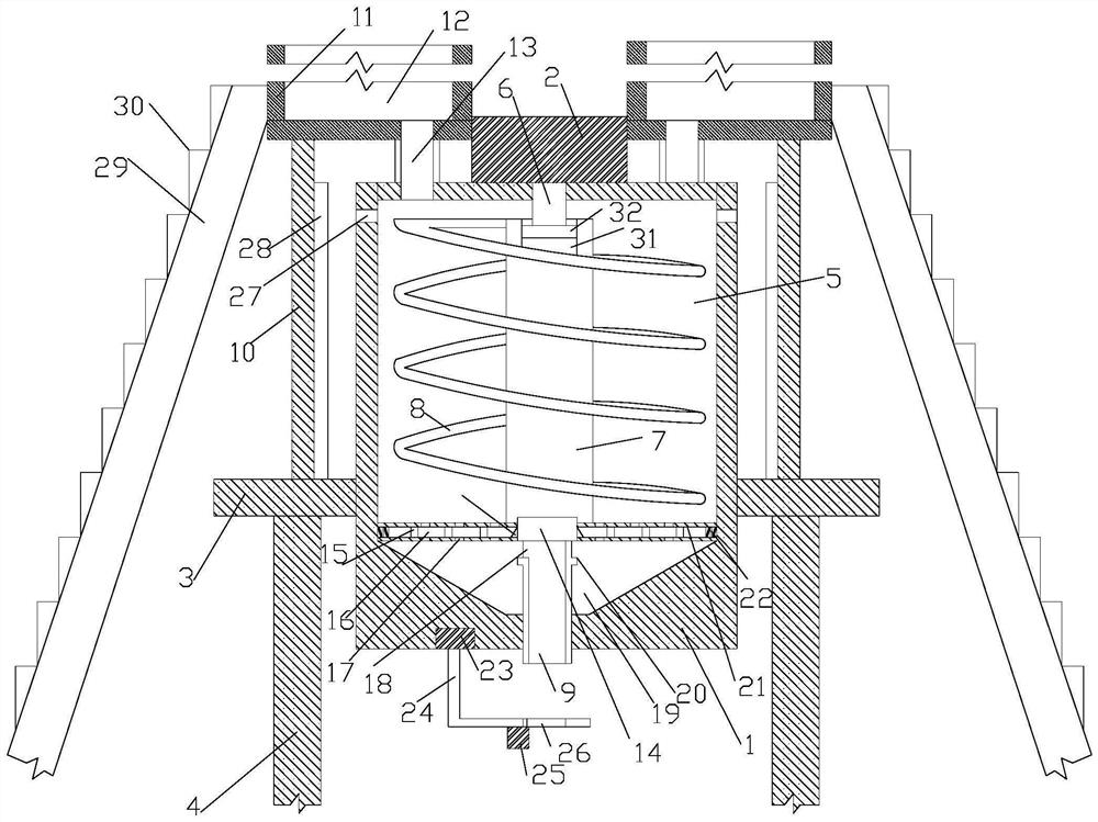
[0014] The present invention proposes a mixing system of a mixing station, comprising a tank body 1, a motor 2 and a support platform 3, the tank body 1 is cylindrical, a support frame 4 is built on the bottom surface, and the support platform 3 is horizontally arranged on the On the support frame 4, the tank body 1 is arranged on the support platform 3, the support platform 3 is horizontal, the support platform has a first through hole, and the tank body 1 passes through the first through hole and fixedly welded on the inner wall of the through hole, the upper surface of the tank body 1 is higher than the support platform 3, the lower surface of the tank body 1 is lower t...


PUM


Abstract

The invention provides a stirring system of a stirring station, which comprises a tank body, a motor and a supporting platform, a supporting frame is erected on the bottom surface, the supporting platform is horizontally arranged on the supporting frame, the tank body is arranged on the supporting platform, the tank body is provided with a stirring cavity, the motor is arranged on the upper surface of the tank body, and an output shaft of the motor penetrates through the tank wall of the tank body, extends into the stirring cavity and is connected with a rotating shaft. A spiral impeller is wound on the rotating shaft, a discharge port is formed in the lower end of the stirring cavity, a supporting rod is arranged on the supporting platform, a plurality of material barrels are arranged on the supporting rod, the outer wall of the motor is fixedly connected with the material barrels, a material cavity of each material barrel is communicated with the stirring cavity through a vertical connecting barrel, and the vertical connecting barrel is provided with a control valve for controlling material passing. Materials enter the stirring cavity along the vertical communicating cylinder, the materials enter the stirring cavity through opening of the control valve, the motor drives the spiral impeller to rotate so as to drive the multiple materials in the stirring cavity to be stirred, and finally the materials are discharged from the discharging port.

Description

technical field [0001] The invention relates to the field of mixing stations, in particular to a mixing system and a mixing method of a mixing station. Background technique [0002] The mixing plant is mainly engaged in the operation of commercial concrete, using cement, fly ash, sand and gravel, water reducing agent and other materials to mix and blend in strict accordance with the national standards, and transport it to the building through a mixer truck (commonly known as "conch truck"). At the construction site, a special concrete pump truck is used to drive the concrete to various building parts; when mixing concrete in a mixing station, the material is usually directly poured into the mixing tank for mixing, and the mixer truck transports the material back and forth, sometimes resulting in a harsh environment. SUMMARY OF THE INVENTION [0003] The problem to be solved by the present invention is to provide a mixing system for a mixing plant in view of the above-ment...

Claims


Application Information

Patent Timeline
IPC IPC(8): B28C5/00B28C9/02B28C5/16B28C7/06B28C7/00
CPCB28C5/006B28C9/02B28C5/16B28C5/0818B28C7/067B28C7/0076Y02W30/91
Inventor 袁林
Owner 重庆国浩永固新型建材有限公司
Why Eureka
Try Eureka