Tight coupling array antenna and network equipment

A technology of tightly coupled arrays and antennas, which is applied in the direction of antennas, antenna arrays, and antenna arrays that are powered independently, and can solve problems such as the failure of single antennas to work normally

Pending Publication Date: 2022-07-01
HUAWEI TECH CO LTD
View PDF8 Cites 1 Cited by
  • Summary
  • Abstract
  • Description
  • Claims
  • Application Information

AI Technical Summary

Problems solved by technology

[0003] The array antenna is widely used because of its high gain. However, since the array antenna integrates multiple antenna elements on one

Method used


Image

  • Tight coupling array antenna and network equipment
  • Tight coupling array antenna and network equipment
  • Tight coupling array antenna and network equipment

Examples


Embodiment Construction

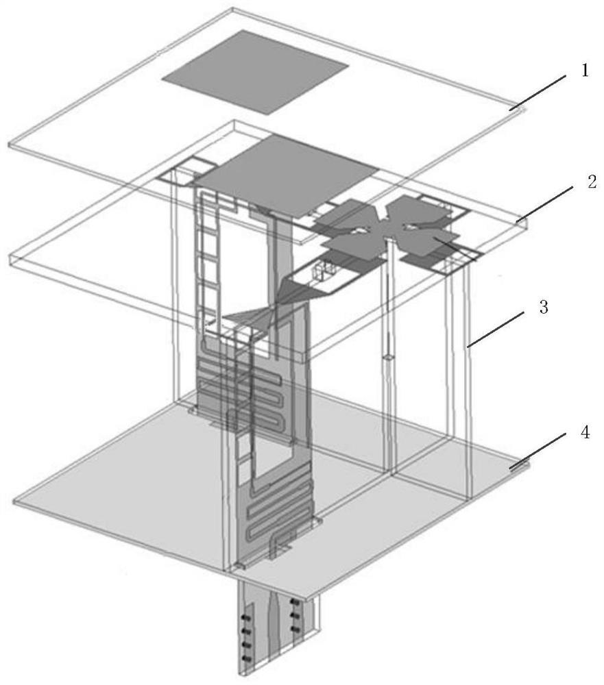
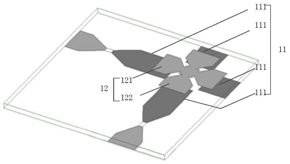
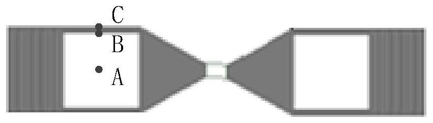
[0045] In order to reduce the active standing wave of the tightly coupled array antenna, a first aspect of the embodiments of the present application provides a tightly coupled array antenna with a novel structure. For details, please refer to figure 1 , figure 1 It is a schematic structural diagram of a tightly coupled array antenna provided according to a feasible embodiment. In the technical solution provided by this embodiment, the tightly coupled array antenna includes at least the first dielectric plate 1 . A plurality of dipole antennas 111 are disposed on the lower surface of the first dielectric plate 1 , and the vibrator arms of the dipole antennas 111 are partially hollowed out. The local hollow design of the vibrator arm of the dipole antenna 111 reduces the capacitance formed between the vibrator arm and the first dielectric plate 1 on the one hand, and on the other hand, reduces the cross-sectional area of ​​the current path and increases the real part of the i...


PUM


Abstract

The embodiment of the invention provides a tight coupling array antenna and network equipment, and the tight coupling array antenna comprises a first dielectric plate, the lower surface of the first dielectric plate is printed with a plurality of antenna units, each antenna unit comprises a plurality of dipole antennas, the dipole antennas are arranged at intervals, and oscillator arms of the dipole antennas are partially hollowed out; a plurality of coupling structures are printed on the upper surface of the first dielectric plate, and each antenna unit is electrically connected with one coupling structure. The tightly coupled array antenna provided by the embodiment at least comprises the first dielectric plate, the lower surface of the first dielectric plate is printed with the plurality of dipole antennas, the oscillator arms of the dipole antennas are locally hollowed out, and the local hollowed-out design of the oscillator arms of the dipole antennas reduces capacitance formed between the oscillator arms and the first dielectric plate on one hand, and reduces the capacitance between the oscillator arms and the second dielectric plate on the other hand; and on the other hand, the sectional area of the current path is reduced to increase the impedance real part, so that the purpose of reducing the active standing wave of the tightly coupled array antenna is achieved.

Description

technical field [0001] The present application relates to the field of mobile communications, and in particular, to a tightly coupled array antenna and network equipment. Background technique [0002] As an important part of the modern wireless communication system, the antenna plays the role of mutual transformation between the guided wave on the transmission line and the electromagnetic wave in the free space, so as to realize the wireless transmission of electromagnetic signals between any two points. An array antenna composed of multiple antenna units in a certain arrangement can use the superposition of electromagnetic waves to strengthen the radiation signal in a specific direction, and is widely used in various fields. A single device with the function of mutual conversion of electromagnetic waves. [0003] Array antennas are widely used because of their high gain. However, since the array antenna integrates multiple antenna monomers into one device, there will be a ...

Claims


Application Information

Patent Timeline
IPC IPC(8): H01Q1/36H01Q1/38H01Q21/00
CPCH01Q21/00H01Q1/36H01Q1/38H01Q9/285H01Q21/062
Inventor 刘祥龙张关喜唐朝阳邹艳林陈栋赵国栋
Owner HUAWEI TECH CO LTD
Why Eureka
Try Eureka