Supercharge Your Innovation With Domain-Expert AI Agents!

Optical fiber identification method, detection device, terminal and network controller

A network controller and detection equipment technology, applied in the field of signal processing, can solve problems such as the difficulty in determining the source and sink information of optical fibers, and the difficulty in label information of optical fibers.

Pending Publication Date: 2022-07-01
HUAWEI TECH CO LTD
View PDF0 Cites 0 Cited by
  • Summary
  • Abstract
  • Description
  • Claims
  • Application Information

AI Technical Summary

Problems solved by technology

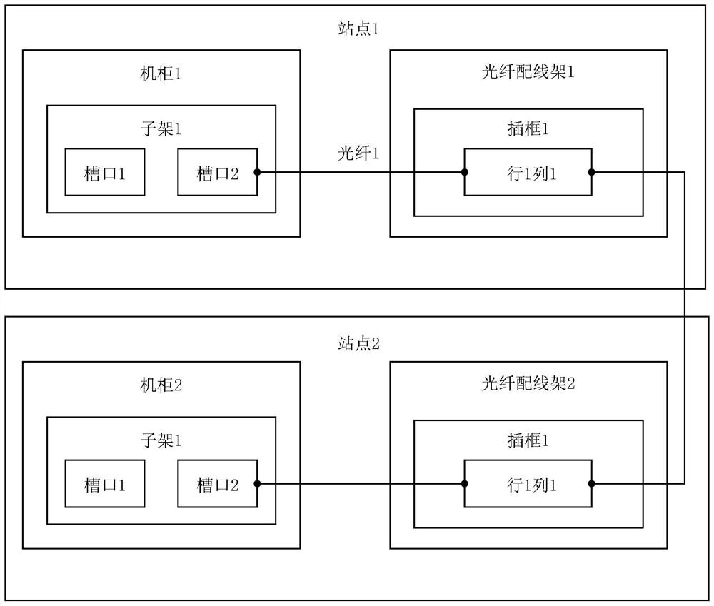
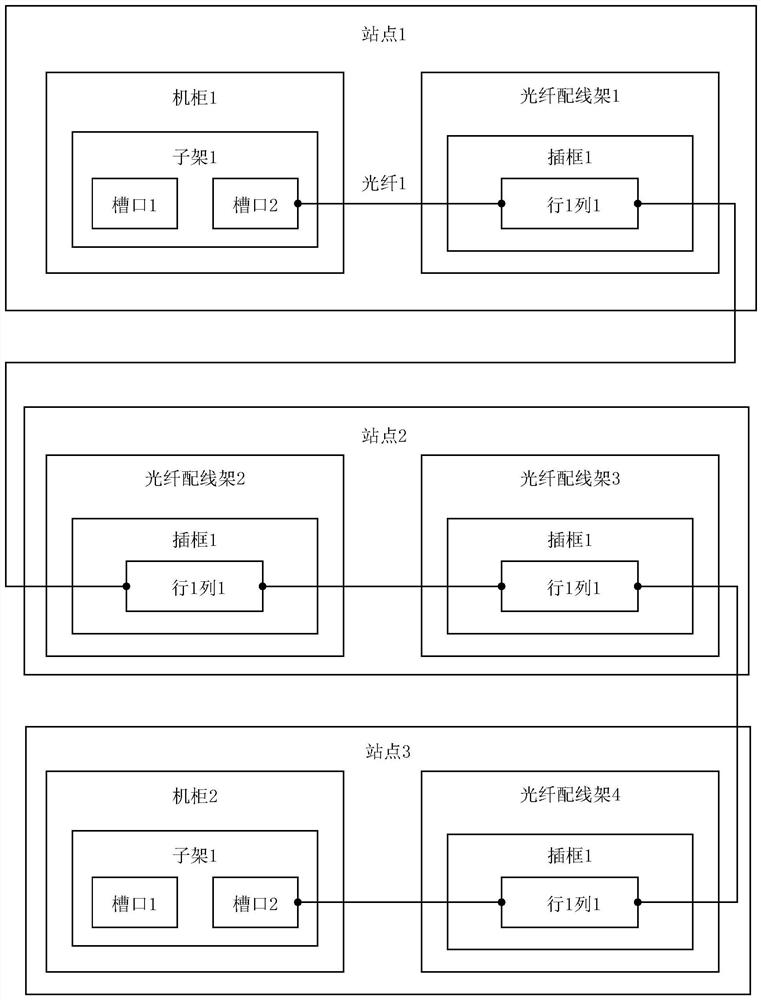
[0004] In the related technology, when the label information of the optical fiber is wrong or the label information is lost because of the aging of the label, the label information of the optical fiber can only be determined manually. Since the transmission equipment of a site has many optical fibers, the label information of the optical fiber can only be determined Information is very difficult
Moreover, when the two sites are not connected by a direct optical fiber, it is difficult to determine the source and sink information of the site where the optical fiber is located by manual investigation.

Method used


Image

  • Optical fiber identification method, detection device, terminal and network controller
  • Optical fiber identification method, detection device, terminal and network controller
  • Optical fiber identification method, detection device, terminal and network controller

Examples


Embodiment Construction

[0066] The embodiment of the present application provides a method for identifying an optical fiber, which is used to acquire the optical fiber information of the optical fiber simply and accurately.

[0067] The embodiments of the present application will be described below with reference to the accompanying drawings. Obviously, the described embodiments are only a part of the embodiments of the present application, but not all of the embodiments. Those of ordinary skill in the art know that, with the development of technology and the emergence of new scenarios, the technical solutions provided in the embodiments of the present application are also applicable to similar technical problems.

[0068] The terms "first", "second" and the like in the description and claims of the present application and the above drawings are used to distinguish similar objects, and are not necessarily used to describe a specific order or sequence. It is to be understood that data so used may be i...


PUM


Abstract

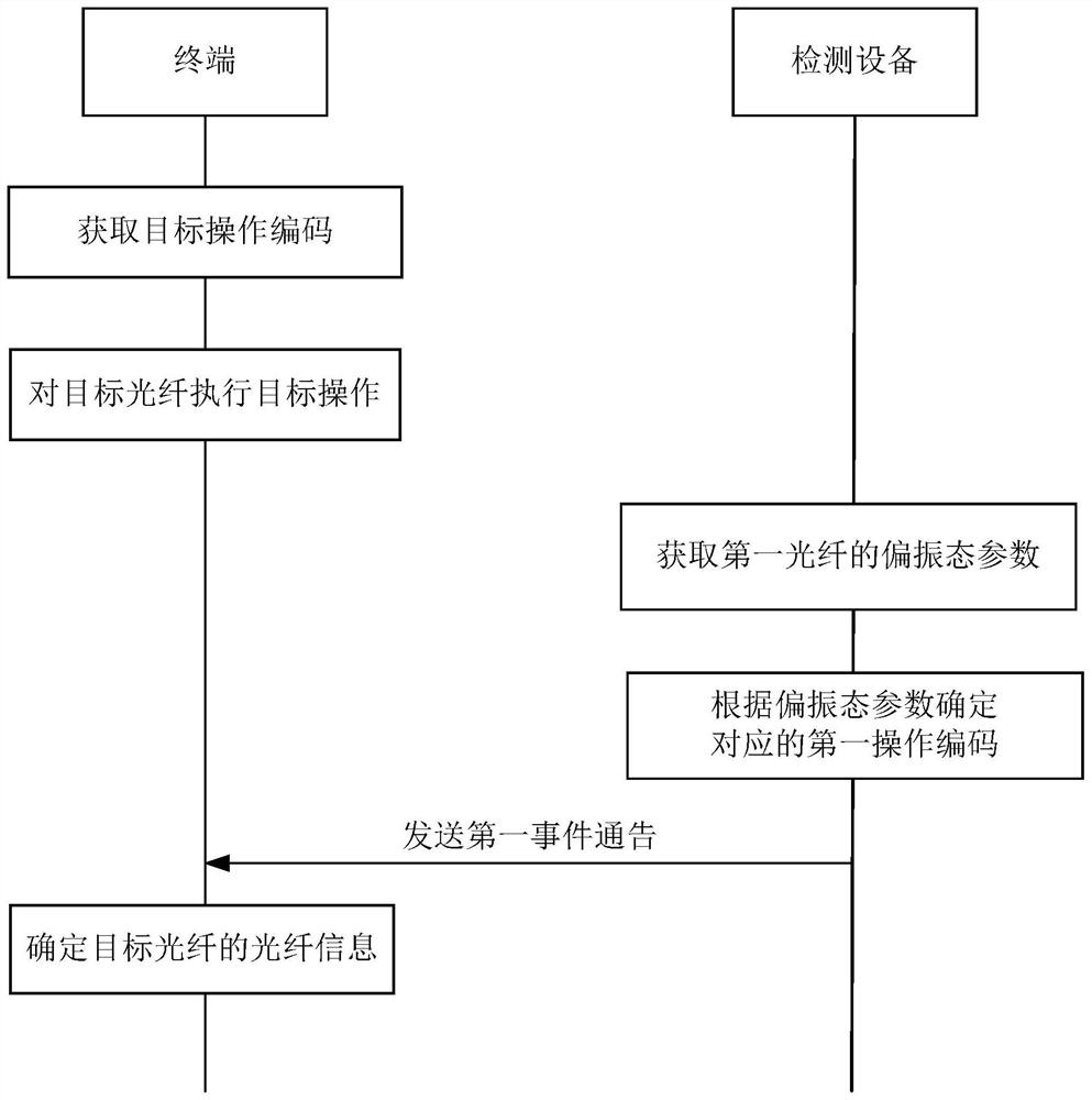
The embodiment of the invention discloses an optical fiber identification method, which is used for simply and accurately acquiring optical fiber information of a target optical fiber. The method comprises the following steps: the detection equipment acquires a polarization state parameter of a first optical fiber; the detection equipment determines a corresponding first operation code according to the polarization state parameter of the first optical fiber, wherein the first operation code indicates a first operation executed by the terminal on the first optical fiber; the detection device then sends a first event announcement, the first event announcement including fiber information of the first optical fiber and the first operation code, the first event announcement being used to determine fiber information of a target optical fiber.

Description

technical field [0001] The embodiments of the present application relate to the field of signal processing, and in particular, to an optical fiber identification method, a detection device, a terminal, and a network controller. Background technique [0002] In an optical communication network, optical fibers are used to connect transmission equipment at two sites. There are usually multiple segments of optical fibers between two transmission devices. Each segment of optical fiber can be connected to an optical fiber distribution frame. The two transmission devices can be connected through the multi-segment optical fiber. [0003] Since each site has multiple transmission devices, and each transmission device needs to be connected to multiple other transmission devices, in order to facilitate maintenance and management, each fiber in the site has a corresponding label, and the information on the label includes the The connection information in the site where the optical fibe...

Claims


Application Information

Patent Timeline
IPC IPC(8): H04B10/079G01M11/00G01H9/00
CPCH04B10/079G01M11/30G01H9/004
Inventor 陈春晖范明惠林毅
Owner HUAWEI TECH CO LTD
Features
  • R&D
  • Intellectual Property
  • Life Sciences
  • Materials
  • Tech Scout
  • Unparalleled Data Quality
  • Higher Quality Content
  • 60% Fewer Hallucinations
Learn More