
Surgical implant mechanical release device and release method

A technology of surgical implants and release devices, applied in medical science, surgery, etc., can solve the problems of short breaking distance, inconvenient holding and dragging by doctors, and small friction, so as to achieve convenient operation and reduce operation time ,Easy to hold and apply force

Pending Publication Date: 2022-07-05
BEIJING AMSINO MEDICAL
View PDF3 Cites 0 Cited by
  • Summary
  • Abstract
  • Description
  • Claims
  • Application Information

AI Technical Summary

Problems solved by technology

However, due to the small diameter of the end catheter, the breaking distance is short, and the friction force is small, it is inconvenient for doctors to hold and drag

Method used


Image

  • Surgical implant mechanical release device and release method
  • Surgical implant mechanical release device and release method
  • Surgical implant mechanical release device and release method

Examples


Embodiment 1

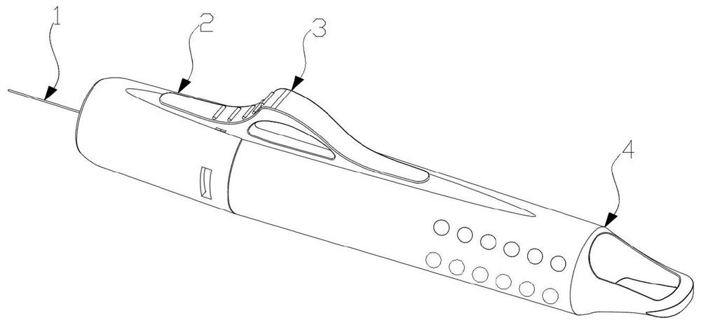
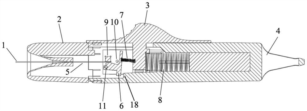
[0056] This embodiment provides a mechanical release device for a spring coil, the device is in the shape of a handle, and its overall connection structure is as follows: figure 1 , its cross-section is shown in figure 2 shown.

[0057] The spring coil mechanical release device includes: push wire, pull back front cover 2, button 3, pull back cover 4, locking device 6, front spring 7, rear spring 8, rectangular block 9, cylindrical rod 10;

[0058] The push guide wire includes an outer tube 1 and a core wire 5, the core wire 5 is arranged inside the outer tube 1, and a part of it extends to the outside of the outer tube 1, and the front end of the push guide wire is connected to the spring coil;

[0059] The pull-back front cover 2 and the pull-back rear cover 4 are respectively hollow structures, and the two are connected to each other to form the body of the spring coil mechanical release device;

[0060] The center of the pull-back front cover 2 is provided with a trumpe...

Embodiment 2

[0068] This embodiment provides a method for mechanically disengaging a spring coil, which is performed by using the mechanical disengaging device for a coil in Embodiment 1, and includes the following steps:

[0069] Pass the core wire 5 into the interior of the pull-back front cover 2 through the through hole, and lock it with the rectangular block 9 through the locking device 6;

[0070] Slide the button 3 backward to pull the locking device 6 and drive the core wire 5 to slide along the axial direction of the mechanical release device of the spring coil, and the through hole blocks the outer tube 1 from the outside of the pull-back front cover 2;

[0071] During the sliding process, when the sliding distance of the core wire 5 relative to the outer tube 1 exceeds the mechanical release stroke of the spring coil, the mechanical release of the spring coil is completed;

[0072] After the mechanical release of the spring coil is completed, slide the button 3 to the front to r...


PUM


Abstract

The invention provides a surgical implant mechanical release device and a release method. The device comprises a pushing guide wire, a pull-back front cover (2), a button (3), a pull-back rear cover (4), a locking device (6), a front spring (7), a rear spring (8) and a rectangular block (9). The pull-back front cover (2) and the pull-back rear cover (4) are connected to form a device body; a through hole is formed in the pull-back front cover (2), and a core wire (5) for pushing a guide wire penetrates through the through hole; the through hole can prevent the outer tube (1) for pushing the guide wire from entering; the locking device (6) and the rectangular block (9) are used for locking the core wire (5); the front spring (7) enables the locking device (6) to clamp the core wire (5) and pull and slide together with the core wire (5) through the button (3), and the slidable distance is larger than the release stroke of the surgical implant. According to the device, the surgical implant can be released only by pushing the button to slide from the near end to the far end, the whole process is convenient and rapid to operate, the operation can be completed by one hand, and the operation time can be effectively shortened.

Description

technical field [0001] The invention relates to a mechanical release device and a release method for surgical implants, belonging to the technical field of medical instruments. Background technique [0002] Intracranial aneurysm refers to a tumor-like protrusion and arteriovenous malformation of the arterial wall caused by the localized abnormal expansion of the lumen of the cerebral arteries. With the rapid development of coil products, embolization of aneurysms is now a popular treatment. In clinical operations, the interventional operation of each aneurysm usually requires several to a dozen coils to complete the dense packing of the aneurysm. On the basis of using a catheter to establish a channel, the packing of each coil needs to go through the steps of conveying, placing, releasing and withdrawing the push rod, and the operation time of the three steps of conveying, placing and releasing is based on the establishment of the channel. Determined by the situation and t...

Claims


Application Information

Patent Timeline
Patent Type & Authority Applications(China)
IPC IPC(8): A61B17/12
CPCA61B17/12031A61B17/12113A61B17/1214A61B2017/12054A61B2017/1205
Inventor 申鑫梁小朋王星雪马晓意周利锋
Owner BEIJING AMSINO MEDICAL
Learn More