A mechanical release coil system with handle

A technology of spring coil and handle, applied in the field of medical equipment

Active Publication Date: 2022-05-31
珠海神平医疗有限公司
View PDF6 Cites 0 Cited by
  • Summary
  • Abstract
  • Description
  • Claims
  • Application Information

AI Technical Summary

Problems solved by technology

[0005] The present invention intends to provide a mechanical release spring coil system with a handle to solve the problem that the mechanical release of the spring coil cannot be completed conveniently and quickly in the prior art

Method used


Image

  • A mechanical release coil system with handle
  • A mechanical release coil system with handle
  • A mechanical release coil system with handle

Examples


Embodiment 1

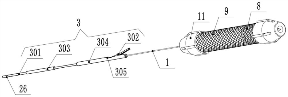
[0059] For the convenience of understanding, in this embodiment, the end close to the operator is defined as the proximal end ( figure 1 the right end of the corresponding handle in the figure 1 Corresponding to the left end of the microcatheter 26 in the middle), the proximal end or the distal end indicated for each component hereinafter refers to the above description.

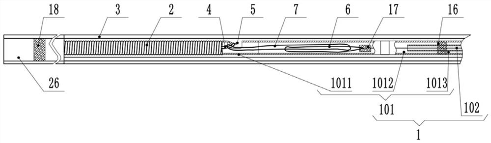
[0060] Embodiment 1 is basically as attached Figure 1-Figure 7 Shown: a mechanical release spring coil system with a handle, including a push guide wire 1 and a spring coil 2 connected to the distal end of the push guide wire 1, the proximal end of the push guide wire 1 is connected with a handle, and also includes a Install the spring coil 2 and push the guide wire 1 into the introducer sheath 3. It should be pointed out that, as a standard part on the market, the microcatheter 26 is a component that needs to be used together with the coil system in the present application during the operation. During th...

Embodiment 2

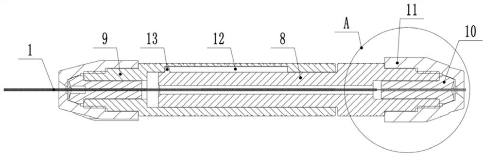
[0082] The difference between the second embodiment and the first embodiment is: as Figure 8 As shown, in this embodiment, the inner wall of the distal handle 9 is provided with a second guide groove 19 staggered from the first guide groove 12, the second guide groove 19 is arranged in parallel with the first guide groove 12, and the first guide groove 19 is arranged in parallel with the first guide groove 12. An annular groove 20 is opened between the distal end of the guide groove 12 and the proximal end of the second guide groove 19. The annular groove 20 spans the circumferential direction of the distal handle 9 with an amplitude of 15° to 345°. In this embodiment, the annular groove 20 spans The amplitude is 20°.

[0083] In the first embodiment, during the disengagement stage of the spring coil 2 (corresponding to step 3), after the disengagement of the spring coil 2 is completed, continue to push image 3 The proximal handle 8 is far away from the distal handle 9 and ...

Embodiment 3

[0085] The difference between the third embodiment and the first embodiment is that in the first embodiment, the proximal end of the distal handle 9 is sleeved outside the distal end of the proximal handle 8, while in this embodiment, as another setting form, such as Figure 9 As shown, the distal end of the proximal handle 8 is sleeved outside the proximal end of the distal handle 9. Correspondingly, the first guide groove 12 is provided on the inner wall of the proximal handle 8, and the protrusion 13 is provided on the inner wall of the proximal handle 8. On the outer wall of the distal handle 9 ( Figure 9 The first guide groove 12 and the protrusion 13 are not shown.


PUM


Abstract

The invention relates to the technical field of medical devices, and specifically discloses a mechanical release coil system with a handle, which includes a pushing guide wire composed of an outer tube and a core wire located in the outer tube, and a coil is connected to the distal end of the pushing guide wire. It also includes a handle, the handle includes a distal handle and a proximal handle that can relatively slide along the axial direction of the push guide wire, the outer tube is connected with the distal handle, and the core wire is connected with the proximal handle; the distal end of the core wire is fixedly connected with a proximal handle. The end wire ring, the middle end wire ring is connected to the cross movable connection on the proximal end wire ring, the distal end wire ring is connected to the spring ring, the middle end wire ring, the distal end wire ring and the outer tube form a mechanical release structure, the proximal end handle and the distal end handle The relative sliding distance is greater than the active distance of the cross movable connection between the middle-end wire ring and the near-end wire ring. The invention solves the problem in the prior art that the mechanical release of the spring coil cannot be accomplished conveniently and quickly by providing a handle and a middle-end wire loop with a movable range.

Description

technical field [0001] The invention relates to the technical field of medical instruments, in particular to a mechanical release spring coil system with a handle. Background technique [0002] Stroke is divided into hemorrhagic stroke and ischemic stroke. Intracranial aneurysm is a hemorrhagic stroke disease with high morbidity and mortality, and is the main cause of subarachnoid hemorrhage. At present, the clinical treatment plan preferred by many medical experts is the most widely used treatment plan under fluoroscopy, using a microcatheter as a surgical channel to embolize aneurysm with coils, thereby preventing aneurysm rupture and hemorrhage. The core of the coil embolization operation lies in the way of releasing the coil. At present, there are mainly three ways of releasing the embolization coil, namely electrolysis, hydrolysis and mechanical release. Among them, the hydrolysis coil has less clinical application due to its poor controllability; most of the electrol...

Claims


Application Information

Patent Timeline
Patent Type & Authority Patents(China)
IPC IPC(8): A61B17/12
CPCA61B17/12113A61B17/1214A61B2017/12054
Inventor 肖相龙王玉峰梁志兴邱海平
Owner 珠海神平医疗有限公司
Why Eureka
Try Eureka