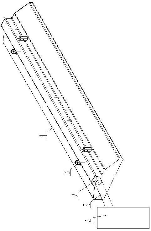
Smoke conveying device and method for plasma numerical control cutting machine

A conveying device and cutting machine technology, applied in the direction of cleaning method using gas flow, plasma welding equipment, chemical instruments and methods, etc., can solve the problems affecting the treatment effect of dust and smoke

Pending Publication Date: 2022-07-05
山东塔高矿业机械装备制造有限公司
View PDF0 Cites 0 Cited by
  • Summary
  • Abstract
  • Description
  • Claims
  • Application Information

AI Technical Summary

Problems solved by technology

[0002] Plasma CNC cutting machine refers to the workpiece instructions or programs used to control machine tools or equipment. It is a new control method given in digital form. When this instruction is provided to the control device of the CNC automatic cutting machine, the cutting machine will It can automatically cut according to the given program. CNC cutting is composed of two parts: CNC system and mechanical structure. When the plasma CNC cutting machine is working, dust and smoke will be generated, so it is used for the smoke of plasma CNC cutting machine The conveying device is an important mechanical process device. Among the existing fume conveying devices for plasma numerical control cutting machines, there is no fume conveying device and method for plasma numerically controlled cutting machines. An overall dust removal system is installed in the working area of ​​the plasma CNC cutting machine. The dust and smoke generated by the plasma CNC cutting machine are released in the working area, and the dust and smoke are absorbed by the overall dust removal system. Due to the combination of the overall dust removal system and the plasma CNC cutting machine The cutting point is at a long distance, which affects the treatment effect of dust and flue gas.

Method used


Image

  • Smoke conveying device and method for plasma numerical control cutting machine
  • Smoke conveying device and method for plasma numerical control cutting machine
  • Smoke conveying device and method for plasma numerical control cutting machine

Examples


Embodiment Construction

[0045]In accordance with the Examining Guidelines, terms such as "having", "comprising" and "comprising" as used herein should be understood as not assigning the presence or addition of one or more other elements or combinations thereof.

[0046] In the description of the present invention, it should be noted that the terms "center", "upper", "lower", "left", "right", "vertical", "horizontal", "inner", "outer", etc. The indicated orientation or positional relationship is based on the orientation or positional relationship shown in the accompanying drawings, which is only for the convenience of describing the present invention and simplifying the description, rather than indicating or implying that the indicated device or element must have a specific orientation or a specific orientation. construction and operation, and therefore should not be construed as limiting the invention. Furthermore, the terms "first", "second", and "third" are used for descriptive purposes only and sh...


PUM


Abstract

A flue gas conveying device and method for a plasma numerical control cutting machine comprises a housing (1) arranged on a cutting nozzle of the plasma numerical control cutting machine and a vacuum fan (4) arranged between the housing (1) and an integral dust removal system, short-distance collection of dust and flue gas is achieved through the housing (1), and the dust and the flue gas are collected through the vacuum fan (4). And the conveying of the dust flue gas to the whole dust removal system is realized, so that the treatment effect on the dust flue gas is improved.

Description

technical field [0001] The invention relates to a flue gas conveying device and method, in particular to a flue gas conveying device and method for a plasma numerical control cutting machine. Background technique [0002] Plasma CNC cutting machine refers to the workpiece instruction or program used to control the machine tool or equipment. It is a new control method given in digital form. When this instruction is provided to the control device of the CNC automatic cutting machine, the cutting machine will It can automatically cut according to the given program. The CNC cutting consists of two parts: the CNC system and the mechanical frame. When the plasma CNC cutting machine is working, dust and smoke will be generated. Therefore, the smoke used for the plasma CNC cutting machine The conveying device is an important mechanical process device. Among the existing flue gas conveying devices for plasma numerical control cutting machines, there is no flue gas conveying device an...

Claims


Application Information

Patent Timeline
Patent Type & Authority Applications(China)
IPC IPC(8): B23K10/00B08B15/04B08B5/04
CPCB23K10/00B08B15/04B08B5/04
Inventor 李宗刚李建敏周海龙宋洪宝纪建忠
Owner 山东塔高矿业机械装备制造有限公司
Why Eureka
Try Eureka