
Container type battery replacing station and battery replacing method thereof

A container-type, power-swap technology, applied in charging stations, electric vehicles, transportation and packaging, etc., can solve the problems of inability to flexibly change the scale of power-swap power stations, high construction cost of fixed power-swap power stations, and high difficulty in disassembly and assembly, and improve space utilization. efficiency, simple installation and low manufacturing cost

Pending Publication Date: 2022-07-05
上海融青新能源科技有限公司
View PDF0 Cites 1 Cited by
  • Summary
  • Abstract
  • Description
  • Claims
  • Application Information

AI Technical Summary

Problems solved by technology

[0003] Usually, the construction cost of the fixed power station is high, and it is difficult to disassemble and assemble. The electric vehicle transportation area is far away from the fixed power station, and a large amount of electric energy is consumed for a round trip.
Moreover, after the existing power exchange station is completed, it cannot be expanded. When the demand for power exchange changes, the scale of the power exchange station cannot be flexibly changed, which is prone to the problem of mismatching supply and demand.

Method used


Image

  • Container type battery replacing station and battery replacing method thereof
  • Container type battery replacing station and battery replacing method thereof
  • Container type battery replacing station and battery replacing method thereof

Examples


Embodiment 1

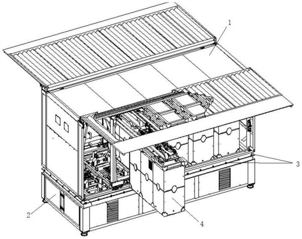
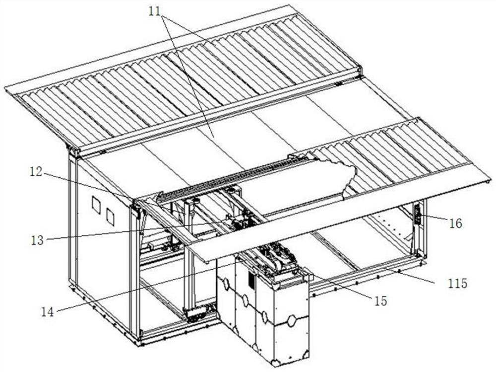
[0066] see Figure 1 to Figure 22 As shown, the embodiment of the present application provides a container-type power exchange station, including: a lower box body 2, an upper box body 1 and a power exchange mechanism. A control device 26 is arranged in the lower box 2 , and a plurality of battery box bases 22 are arranged on the lower box 2 along the length direction. The upper case 1 is detachably connected to the lower case 2 , and the upper case 1 and the lower case 2 are enclosed to form a cavity for accommodating the battery case base 22 . The power exchange mechanism is movably disposed in the cavity, and the power exchange mechanism is connected with the control device 26 . The control device 26 can control the power exchange mechanism to perform the power exchange action.

[0067] The containerized power exchange station of the present application includes a lower box body 2 and an upper box body 1. During the assembly process, the lower box body 2 and the upper box...

Embodiment 2

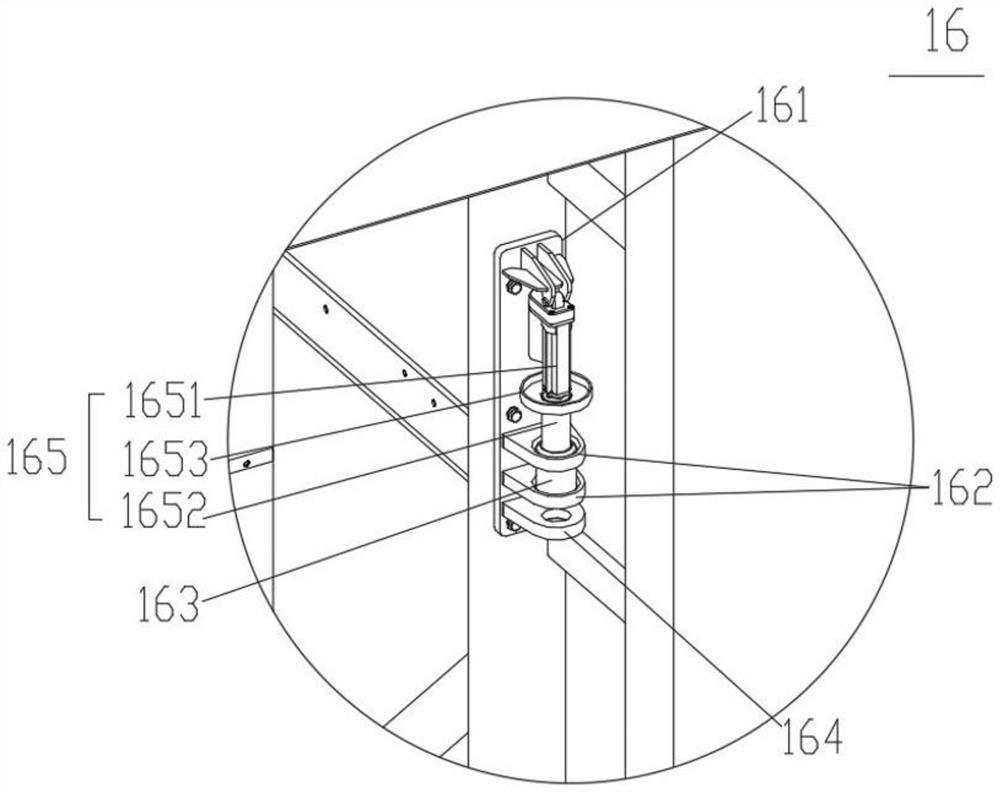
[0090] see figure 2 and image 3 As shown, the second embodiment of the present application further describes the containerized power exchange station in detail on the basis of the first embodiment. The containerized power exchange station further includes an anchoring device 16 for locking or releasing the power exchange mechanism on the power exchange station. The guide sleeve 163 is connected to the mounting plate 161 , and the guide sleeve 163 has a guide groove therethrough. The support member 164 is connected to the mounting plate 161 , and the support member 164 has a limit hole. The telescopic device 165 includes a fixed part 1651 and a telescopic part 1652 , the fixed part 1651 is connected to the mounting plate 161 , and the telescopic part 1652 is movably connected to the fixed part 1651 . The anchoring device 16 has a locked state and a released state. In the released state, the telescopic portion 1652 is accommodated in the guide groove; in the locked state, the...

Embodiment 3

[0104] see image 3 As shown, on the basis of the above-mentioned embodiments, the third embodiment of the present application further describes a power exchange station, which further includes: a hydraulic pipe accommodating device 171 and a movable hydraulic pipe. The power exchange mechanism is movably connected to the power exchange station, the power exchange mechanism can translate along the length direction of the power exchange station, and the power exchange mechanism has a hydraulic drive mechanism 128 . The hydraulic pipe accommodating device 171 is connected to the power exchange station. The movable hydraulic pipe is partially accommodated in the hydraulic pipe accommodating device 171 , and the movable hydraulic pipe is connected to the hydraulic drive mechanism 128 . When the power exchange mechanism is moving away from the hydraulic pipe accommodating device 171 , the movable hydraulic pipe can be driven to extend out of the hydraulic pipe accommodating device...


PUM


Abstract

The invention discloses a container type battery replacing station and a battery replacing method thereof. The container type battery replacing station comprises a lower box body, an upper box body and a battery replacing mechanism. Control equipment is arranged in the lower box body, and a plurality of battery box bases are arranged on the lower box body in the length direction. The upper box body is detachably connected to the lower box body, and the upper box body and the lower box body are enclosed to form a cavity for accommodating a battery box. The battery replacing mechanism is movably arranged in the cavity, and the battery replacing mechanism is connected with the control device. The container type battery replacing station comprises the lower box body and the upper box body, and in the assembling process, the station can be rapidly built by sequentially hoisting the lower box body and the upper box body. And the control equipment is arranged on the lower box body, the space of the upper box body is not occupied, and the space utilization rate is increased. The container type battery replacing station is convenient to move, easy to install and low in manufacturing cost, module combination is achieved, the station building cost is remarkably reduced, and the container type battery replacing station is suitable for wide popularization.

Description

technical field [0001] The invention relates to the technical field of new energy equipment, in particular to a containerized power exchange station and a power exchange method thereof. Background technique [0002] With the development of new energy vehicles, the demand for electric energy of electric vehicles is becoming more and more urgent, and the power exchange station has become an inevitable trend of development. Generally, there are multiple battery boxes arranged on the power exchange station, and a power exchange mechanism is installed on the power exchange station. When it is necessary to change the power, it is necessary to travel to the power exchange station, and the power exchange mechanism on the power exchange station can perform the power exchange action, to replace the battery box with insufficient power on the equipment to be replaced to the power exchange station, and to replace the fully charged battery on the power exchange station. Boxes are transfer...

Claims


Application Information

Patent Timeline
Patent Type & Authority Applications(China)
IPC IPC(8): B60L53/80
CPCB60L53/80Y02T10/70Y02T10/7072
Inventor 杨轶蔡宁郭鹏
Owner 上海融青新能源科技有限公司
Learn More