
Arched cavity fluid flowing floor slab, manufacturing method and flowing pipe

A technology of fluid flow and flow pipes, which is applied to floors, manufacturing tools, building structures, etc., can solve the problems of difficulty in meeting low-carbon requirements, smoke exhaust, high ventilation costs, airflow pressure loss, etc., to reduce the amount of concrete and shorten the Construction period and effect of reducing local pressure loss

Active Publication Date: 2022-07-05
CHINA UNIV OF MINING & TECH
View PDF8 Cites 0 Cited by
  • Summary
  • Abstract
  • Description
  • Claims
  • Application Information

AI Technical Summary

Problems solved by technology

[0004] Existing cavity floor slabs, for example, the patent number is: 202110869646.3 patent of invention discloses the scheme "a multifunctional cavity floor, the cavity floor includes a plurality of cavity floors combined with each other, the cavity There are single or multiple multi-functional cavities inside the floor. When the inside of the cavity floor is a single cavity, there are openings for connection around the floor. Multiple single-cavity floors are connected to each other through openings to form a flue; When there are multiple cavities inside the cavity floor, the cavities in the cavity floor are connected to each other by setting through holes between the beams to form a flue.” The flue structure of the above scheme has obvious sudden expansion and contraction structures , when the flue gas flows in the flue, the air flow pressure will be lost due to the change of the flue volume, the energy attenuation phenomenon is serious, and it is easy to cause the exhaust and ventilation costs to be too high, and it is difficult to meet the low-carbon requirements

Method used


Image

  • Arched cavity fluid flowing floor slab, manufacturing method and flowing pipe
  • Arched cavity fluid flowing floor slab, manufacturing method and flowing pipe
  • Arched cavity fluid flowing floor slab, manufacturing method and flowing pipe

Examples


Embodiment 1

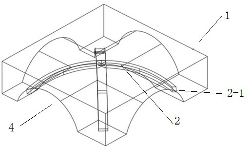
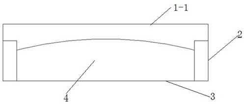
[0039] like figure 1 As shown, an arched cavity fluid flow floor 1, the floor 1 is a cube structure, a horizontal top plate is arranged above the floor 1, the top plate can be used as the floor or roof plate of the upper floor, and the bottom surface of the floor 1 is provided with an arc The side of the arc-shaped groove is provided with a groove 4 that communicates the groove with the outside of the floor 1. The depth of the groove 4 matches the depth of the groove, and the arc-shaped groove corresponds to the four lateral positions of the floor 1. There is a groove 4 communicating with the side surface. There is a supporting surface at the bottom of the floor 1, and the floor 1 and the supporting surface form a box structure with a cavity and a pipeline inside. The angle is consistent with the radian of the groove, and the two arched beams 2 arranged in a cross can form an included angle of 30° to 90° as required, and the two arched beams 2 are both arched structures with ...

Embodiment 2

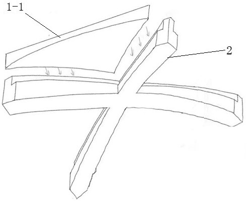
[0043] The manufacturing method of the arched cavity fluid flow floor slab, the manufacturing steps are as follows:

[0044] S1. According to the size in the design requirements, make the mold of the arc-splitting plate and the arched beam plate 2, inject concrete into the mold, and continue to stir and shake until the concrete is uniform without air bubbles, and continue to add concrete until it is full;

[0045] S2. After the concrete is solidified, demould, and take out four arc-parting slabs and two arched beam slabs 2;

[0046] S3. Assemble the four arc-shaped slabs and the two arched beam slabs 2. When splicing, build both sides of one arc-shaped slab on the two arched girder slabs 2, and then place it with the first arc-shaped slab. The arc-splitting plate position in the symmetrical position, and finally place the remaining two arc-splitting plates;

[0047] S4. Inject adhesive into the gap between the assembled four arc-parting plates and the root arch beam plate 2 to ...

Embodiment 3

[0054] like Figure 5 As shown, a flow tube is formed according to an arched cavity fluid flow floor, the flow tube is formed by arranging a plurality of floor slabs 1, one end of the flow tube is located at the edge of the floor, and the floor 1 located at the edge of the floor is close to the floor. One side of the wall is provided with a through pipe that communicates with the outside, and the through pipe is provided with a pressurizing device. If the flowing medium in the flow pipe is gas, the pressurizing device can be an air pump, a fan, etc.; if the flowing medium in the flow pipe is a liquid Then the pressurizing device is a high-pressure water pump; an opening is provided in the ceiling 3 of the floor 1 slab at the other end of the flow pipe, and the opening 4 of the butt joint between two adjacent floor slabs 1 in the flow tube is aligned to form a fluid flow channel, and the floor 1 The outer sides of the openings 4 corresponding to both sides of the fluid flow cha...


PUM


Abstract

The invention relates to the field of buildings, and discloses an arch-shaped cavity fluid flowing floor slab, an arc-shaped groove is formed in the bottom surface of the floor slab, a groove enabling the groove to be communicated with the outer side of the floor slab is formed in the side part of the arc-shaped groove, the depth of the groove is close to that of the groove, and a supporting surface is arranged at the bottom of the floor slab. A groove is formed in the floor, the floor and the supporting face form a box body structure, a cavity and a pipeline are arranged in the box body structure, two arched beam plates which are arranged in a crossed mode are arranged in the groove, the bending degree of the arched beam plates is consistent with the radian of the groove, and beam feet at the two ends of the arched beam plates are fixedly connected with the supporting face. The concrete consumption is reduced, the bearing capacity of the whole structure is improved, reinforcing steel bars do not need to be embedded into the floor slab for reinforcement, the flowing pipe formed by arranging the floor slabs has no obvious sudden expansion and sudden shrinkage structures, local pressure loss in the flowing process of airflow or water flow is effectively reduced, and the efficiency of fluid flowing work such as smoke exhaust, ventilation and water drainage is remarkably improved.

Description

technical field [0001] The invention relates to the field of construction, in particular to an arched cavity fluid flow floor, a manufacturing method and a flow pipe. Background technique [0002] With the continuous improvement of social progress and productivity level and the development of personalization, people pay more and more attention to the quality of living, and put forward higher requirements for buildings, hoping for better comfort and freedom, which is a challenge for structural designers That is, lighter weight, more reasonable floor height and better mechanical properties, etc., to meet customers' expectations of obtaining the best benefits and functions in a limited building space. [0003] In ordinary reinforced concrete structures, the dead weight of the floor is about 30%~40% of the total dead weight. In reinforced concrete high-rise structures, the dead weight of the floor is about 50%~60% of the total dead weight, while in large-span buildings In the m...

Claims


Application Information

Patent Timeline
Patent Type & Authority Applications(China)
IPC IPC(8): E04B5/43E04B5/48B28B13/02B28B13/06B28B1/08
CPCE04B5/43E04B5/48B28B13/02B28B13/06B28B1/08Y02B30/00
Inventor 王勇古傲林刘伟鑫王姗姗王昕鹤孟子扬王功臣部翼翔任兆卿
Owner CHINA UNIV OF MINING & TECH
Learn More