Intelligent well completion underground digital hydraulic communication controller

A technology that communicates with the controller and intelligent well completion. It is applied in the directions of wellbore/well components, wellbore/well valve devices, sealing/packing, etc. It can solve the problems of difficult surface hydraulic operations, loss of identification of hydraulic signals, Problems such as the inability of the valve core to move can be achieved to reduce the difficulty of mechanical processing, simplify the internal structure of the valve body, and enhance the working reliability.

Active Publication Date: 2022-07-05
XI'AN PETROLEUM UNIVERSITY
View PDF3 Cites 0 Cited by
  • Summary
  • Abstract
  • Description
  • Claims
  • Application Information

AI Technical Summary

Problems solved by technology

This kind of hydraulic decoder has the following problems: First, due to the pressure loss on the long hydraulic pipeline in the well, the actual hydraulic force of the low-pressure unlocking hydraulic force loaded on the wellhead is less than the unlocking hydraulic force after being transmitted to the downhole hydraulic decoder, causing the lock The unlocking slot on the sleeve has not moved to the center of the locking ball, and the locking ball is still stuck in the slot on the spool to lock the spool so that the unlocking fails, and the spool cannot move under high-pressure hydraulic force; when the wellhead is loaded The hydraulic force is greater than the unlocking hydraulic force. After being transmitted to the downhole hydraulic decoder through the downhole long hydraulic pipeline, the actual hydraulic force is greater than the unlocking hydraulic force, causing the unlocking groove on the lock sleeve to move beyond the center of the locking ball, and the locking ball is still stuck Locking the spool in the card slot on the spool makes the unlocking invalid. The spool cannot move under high-pressure hydraulic force. It is very likely that the unlocking failure will be caused by ground hydraulic operation errors. Therefore, the single lock sleeve structure requires precise loading of low pressure at the wellhead. The unlocking hydraulic value can ensure that the unlocking groove on the lock sleeve moves to the center of the locking ball, and the hydraulic operation on the ground is more difficult. Secondly, due to the unlocking hydraulic channel of the lock sleeve and the opening or closing hydraulic channel of the flow control valve The opening or closing hydraulic force of the flow control valve is much greater than the unlocking hydraulic force of the lock sleeve. The lock sleeve has no positioning structure and cannot effectively protect the lock sleeve spring. The lock sleeve moves directly under the opening or closing hydraulic force of the flow control valve. The spring of the lock sleeve is compressed to the end, and the spring of the lock sleeve is over-fatigued and prone to elastic failure after repeated compressions, resulting in the failure of the lock sleeve to return to the initial position, resulting in the failure of the valve core to lock, and the downhole hydraulic decoder loses the function of identifying the hydraulic signal. In the process of identifying the hydraulic signal, the lock sleeve spring needs to be repeatedly compressed by two stages. During the long-term underground work, the lock sleeve spring is extremely easy to fatigue and fail to cause the valve core to lock and fail. Fourth, use another way of hydraulic pipeline pressure The auxiliary lock sleeve resets the initial position to increase the surface hydraulic operation procedure, and these problems reduce the reliability of the overall operation of the downhole hydraulic decoder

Method used


Image

  • Intelligent well completion underground digital hydraulic communication controller
  • Intelligent well completion underground digital hydraulic communication controller
  • Intelligent well completion underground digital hydraulic communication controller

Examples


Embodiment Construction

[0030] The present invention will be further described in detail below with reference to the accompanying drawings and examples, but the present invention is not limited to the following embodiments.

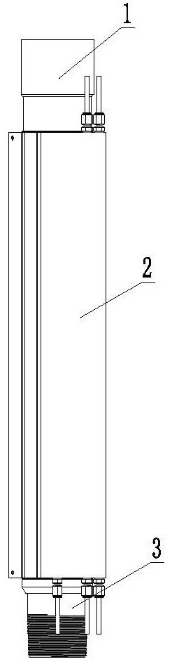
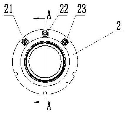
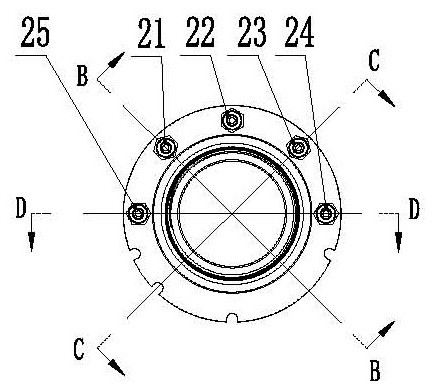
[0031] exist Figures 1 to 7 Among them, the intelligent downhole digital hydraulic communication controller of this embodiment consists of an upper joint 1, a valve body 2, a lower joint 3, an annular seat 4, a first return spring 5, a piston 6, a lock sleeve 7, and a second return spring 8; The sealing plug 9 is connected to form.

[0032]The central hole of the valve body 2 is composed of a first cylindrical hole, a second cylindrical hole, and a third cylindrical hole connected in sequence from top to bottom. The diameter of the first cylindrical hole is larger than the diameter of the second cylindrical hole, and the first cylindrical hole The connection between the cylindrical hole and the second cylindrical hole is processed with chamfering as the locking sleeve stop str...


PUM


Abstract

An intelligent well completion underground digital hydraulic communication controller is characterized in that an upper connector is arranged at one end of a valve body, a lower connector is arranged at the other end of the valve body, a piston is arranged in the valve body, the two ends of the piston extend into the upper connector and the lower connector respectively, piston stop structures are arranged in the upper connector and the lower connector respectively, and a lock sleeve is arranged between the piston and the valve body; a first reset elastic structure body is sleeved on the piston in a seventh hydraulic cavity formed between the upper part of the lock sleeve and the piston; a sixth hydraulic cavity formed by a first radial groove and the lock sleeve, a fifth hydraulic cavity formed by a second radial groove and the lock sleeve, a fourth hydraulic cavity formed by a third radial groove and the lock sleeve and a second hydraulic cavity formed by a fourth radial groove and the lock sleeve are sequentially machined in the outer side wall of the valve body. A fifth radial groove is machined in the position, located on the inner side of the fourth hydraulic cavity, of the lock sleeve and forms a third hydraulic cavity with the piston, a first hydraulic cavity is formed between the piston below the lock sleeve in the axial direction and the valve body, a lock sleeve locking structure is arranged on the valve body in the first hydraulic cavity, and the piston is sleeved with a second reset elastic structure body.

Description

technical field [0001] The invention belongs to the technical field of equipment for extracting oil, gas, water, dissolvable or meltable substances or mineral mud from wells, and particularly relates to a digital hydraulic communication controller for well completion downhole. Background technique [0002] After years of development, domestic intelligent completion technology has been widely used in nearly a thousand oil and water wells in more than ten oilfields in China. The hydraulic sliding sleeve reversing movement of the downhole flow control valve of the hydraulically controlled intelligent completion system to open and close the valve holes at all levels is the key core technology to realize the downhole fluid control. [0003] At present, the domestic hydraulically controlled intelligent completion systems all use the N+1 method to directly control N downhole flow control valves, that is, N downhole flow control valves require N open oil inlet hydraulic pipelines an...

Claims


Application Information

Patent Timeline
Patent Type & Authority Applications(China)
IPC IPC(8): E21B34/08
CPCE21B34/08E21B2200/06Y02E10/10
Inventor 毕刚王金龙王玲云杨梁栋张冰程嘉瑞王樱茹武宇琛陈潇潇刘增辉
Owner XI'AN PETROLEUM UNIVERSITY
Why Eureka
Try Eureka