
Refrigerant uniform distribution system of liquefied natural gas (LNG) coiled tube heat exchanger

A technology of heat exchanger and coiled tube, which is applied in the field of LNG coiled tube heat exchanger refrigerant uniform distribution system, which can solve the problems of application, inability to use floating liquefied natural gas production technology, poor uniformity, etc., and achieve atomized droplets Small, the effect of suppressing uneven distribution of refrigerant and the effect of small flow pressure drop

Pending Publication Date: 2022-07-05
CNOOC GAS & POWER GRP
View PDF0 Cites 0 Cited by
  • Summary
  • Abstract
  • Description
  • Claims
  • Application Information

AI Technical Summary

Problems solved by technology

[0008] In view of the above technical problems, the present invention provides a LNG coiled heat exchanger refrigerant uniform distribution system. The LNG coiled heat exchanger uniform distribution system can be used in land and ocean liquefied natural gas production processes, and can work in long-term sloshing environments. And the uniformity is good, which is conducive to high heat exchanger operation efficiency, and solves the problem that the existing LNG coiled heat exchanger uniform distributor can only be applied to the land environment, cannot be used in the floating liquefied natural gas production process, and has poor uniformity

Method used


Image

  • Refrigerant uniform distribution system of liquefied natural gas (LNG) coiled tube heat exchanger
  • Refrigerant uniform distribution system of liquefied natural gas (LNG) coiled tube heat exchanger
  • Refrigerant uniform distribution system of liquefied natural gas (LNG) coiled tube heat exchanger

Examples


Embodiment Construction

[0039] In order to make the purpose, technical solutions and advantages of the present invention clearer, the technical solutions in the present invention are described clearly and completely below. Obviously, the described embodiments are part of the embodiments of the present invention, not all of the embodiments. Based on the embodiments of the present invention, all other embodiments obtained by persons of ordinary skill in the art without creative efforts shall fall within the protection scope of the present invention.

[0040] Unless otherwise defined, technical or scientific terms used in the present invention should have the ordinary meaning as understood by one of ordinary skill in the art to which the present invention belongs. The terms "first," "second," "third," "fourth," and similar terms used herein do not denote any order, quantity, or importance, but are merely used to distinguish the various components. "Comprising" or "comprising" and similar words mean that...


PUM


Abstract

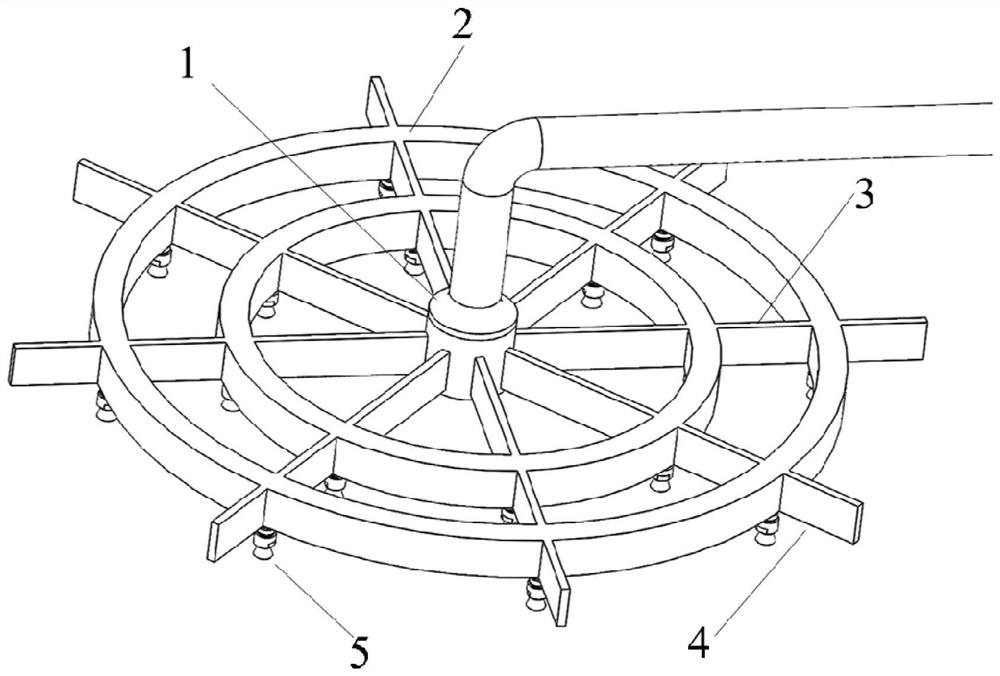
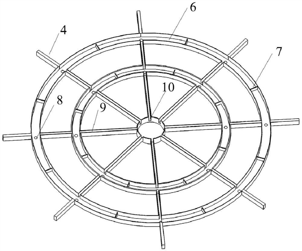
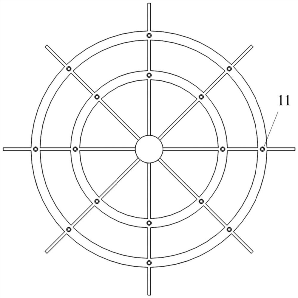
The invention relates to an LNG wound tube heat exchanger refrigerant uniform distribution system which comprises a center cylinder of a hollow cylindrical structure, an opening connected with a refrigerant pipeline is formed in the center cylinder, and a plurality of center cylinder liquid outlets are evenly formed in the side wall of the center cylinder in the circumferential direction; the distribution arms are of hollow tubular structures, openings connected with the liquid outlets of the center cylinder are formed in the distribution arms, and the distribution arms and the liquid outlets of the center cylinder are arranged in a one-to-one correspondence mode; the plurality of distribution rings are of hollow annular structures, the plurality of distribution rings radiate outwards by taking the central cylinder as the center and are in fluid conduction connection with the plurality of distribution arms, and a plurality of distribution ring liquid outlet holes are uniformly formed in the bottom wall of each distribution ring; and the plurality of uniformly distributed nozzles are arranged in one-to-one correspondence with the plurality of distribution ring liquid outlet holes. The system can be used for land and ocean liquefied natural gas production processes, can work in a long-term sloshing environment, is good in uniformity, and facilitates high operation efficiency of a heat exchanger.

Description

technical field [0001] The invention relates to a refrigerant uniform distribution system for an LNG coiled-tube heat exchanger, which belongs to the technical field of coiled-tube heat exchangers. Background technique [0002] The coiled tube heat exchanger is a compact partition heat exchanger, which has the advantages of high pressure resistance, high heat transfer efficiency, fast start-up speed, etc. Onshore and offshore natural gas liquefaction processes. A distributor is often installed at the inlet of the coiled tube heat exchanger to evenly distribute the refrigerant to the coiled tubes. Therefore, the performance of the coiled tube heat exchanger has a great dependence on the uniform distribution performance of the homogenizer. When the refrigerant flow distribution of the homogenizer is uneven, it is easy to cause the heat exchange efficiency of the heat exchanger to decrease. [0003] At present, the homogenizers of LNG coiled tube heat exchangers mostly adopt ...

Claims


Application Information

Patent Timeline
IPC IPC(8): F28F9/22F28F25/06
CPCF28F9/22F28F25/06
Inventor 密晓光陈杰高玮杨文刚程昊盖小刚范明龙李玥
Owner CNOOC GAS & POWER GRP
Learn More