Low-delay monitoring device and method for 256*256 switching matrix

A switching matrix and monitoring device technology, applied in the field of electronic information, can solve the problems of low system work efficiency, high real-time performance, and time delay amplification, and achieve the effects of optimizing real-time monitoring, reducing monitoring time delay, and improving work efficiency

Pending Publication Date: 2022-07-05
江苏肯立科技股份有限公司
View PDF0 Cites 0 Cited by
  • Summary
  • Abstract
  • Description
  • Claims
  • Application Information

AI Technical Summary

Problems solved by technology

Serial communication needs to transmit and receive commands bit by bit at the rate agreed by both parties. The communication delay is affected by the length of the command, the running speed of the IC, and the processing speed of the CPU. When facing a large-scale switching matrix, the delay will be amplified, which will reduce the working efficiency of the system. Decline in user experience
[0005] like figure 1 , the monitoring link in the traditional switching matrix is ​​usually composed of "monitoring terminal CPU + monitoring terminal communication IC" and "monitored terminal CPU + monitored terminal communication IC". When the switching matrix switching scale is small, the impact of delay is small, and the real-time performance is high. For example, a 4×8 switching matrix has 32 port switching combinations, and the full-load tour switching time is “32×(CPU instruction processing time Delay + CPU instruction transmission baud rate × byte + communication IC enabling time + communication IC instruction transmission delay)", the transmission speed of the signal in the metal carrier is approximately equal to the speed of light, and the delay is negligible. The CPU uses a 128MHz high-speed clock, and the transmission The baud rate is 115200 according to the conventional value, the number of bytes is 8, the enabling time of the communication IC is about 7μs, and the transmission delay of the communication IC command is about 0.5μs. In summary, the 4×8 switching matrix is ​​fully loaded with a round-robin switching time of about 18ms ; There are 65536 port switching combinations in the 256×256 switching matrix. After converting the switching time of the 4×8 switching matrix, the full-load tour switching time is about 36.9s, which seriously affects the system work efficiency and user experience.

Method used


Image

  • Low-delay monitoring device and method for 256*256 switching matrix
  • Low-delay monitoring device and method for 256*256 switching matrix
  • Low-delay monitoring device and method for 256*256 switching matrix

Examples


Embodiment Construction

[0025] The technical solutions of the present invention will be further explained below with reference to the accompanying drawings.

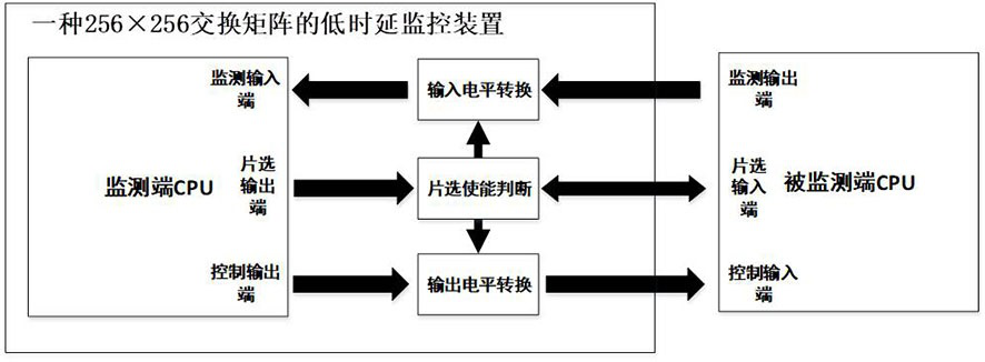
[0026] like figure 2 It is a schematic diagram of the low-latency monitoring device of the 256×256 switching matrix of the present invention. The 256×256 switching matrix low-latency monitoring device is connected to the 256×256 switching matrix. The monitoring interface of the monitoring device is the same, and the monitoring circuits of all channels / boards adopt the parallel Pin-to-Pin method; 256×256 switching matrix low-latency monitoring device and 256×256 switching matrix power supply. The low-latency monitoring device of the 256×256 switching matrix shortens the full-load patrol switching time from 36.9s to 528ms, which greatly reduces the monitoring delay, improves the work efficiency of the 256×256 switching matrix system, and optimizes the real-time monitoring of the switching matrix. sex.

[0027] The 256×256 switching matrix low...


PUM


Abstract

The invention discloses a low-delay monitoring device for a 256 * 256 switching matrix, which comprises a monitoring end CPU (Central Processing Unit), an input level conversion circuit, a chip selection enabling judgment circuit and an output level conversion circuit, and is characterized in that the output end of the input level conversion circuit is connected with the monitoring input end of the monitoring end CPU; the input end of the input level conversion circuit is connected with the monitoring output end of the monitored end CPU, the input end of the chip selection enabling judgment circuit is connected with the chip selection output end of the monitored end CPU, and the output end of the chip selection enabling judgment circuit is connected with the chip selection input end of the monitored end CPU. The input end of the output level conversion circuit is connected with the control output end of the monitoring end CPU; the chip selection enabling judgment circuit is respectively connected with the input level conversion circuit and the output level conversion circuit, and the output end of the output level conversion circuit is connected with the control input end of the monitored end CPU. According to the low-delay monitoring device, the switching matrix monitoring delay is greatly reduced.

Description

technical field [0001] The invention relates to the technical field of electronic information, and in particular, to a low-latency monitoring device and method for a 256×256 switching matrix. Background technique [0002] In satellite communication, switching matrix is ​​a crucial device for signal distribution and forwarding during signal transmission on the ground. It can route different signals from different cables to one or more devices for processing or testing operations, which improves the automation of signal routing and improves the efficiency of the signal transmission process. [0003] Typically, satellite signals are transmitted from space to Earth at different frequencies and polarizations between the satellite and the ground station antenna. After the satellite signal is received by the antenna, it is separated and the signal is fed to a low noise downconverter, which will typically become L-band or extended L-band. Next, the frequency-converted signal will ...

Claims


Application Information

Patent Timeline
Patent Type & Authority Applications(China)
IPC IPC(8): G06F13/366G06F13/42G06F13/40H04Q1/02H04Q1/20H04Q1/28H04B7/185
CPCG06F13/366G06F13/4221G06F13/4022G06F13/4068H04Q1/028H04Q1/20H04Q1/28H04B7/18517G06F2213/0004
Inventor 陈世昌奚盎
Owner 江苏肯立科技股份有限公司
Why Eureka
Try Eureka