Detachable nested composite superconducting cavity

A superconducting cavity and nested technology, which is applied in the field of radio frequency superconductivity, can solve difficult problems such as processing, and achieve the effects of reduced maintenance costs, reduced volume, and reduced processing difficulty

Pending Publication Date: 2022-07-05
INST OF MODERN PHYSICS CHINESE ACADEMY OF SCI
View PDF0 Cites 2 Cited by
  • Summary
  • Abstract
  • Description
  • Claims
  • Application Information

AI Technical Summary

Problems solved by technology

Moreover, the beam tube is also welded to the general superconducting cavity during processing, and a sealing device is added on the side of the beam tube after forming. The sealing ring of the required device also needs superconducting materials, and generally only expensive and difficult Processed metal indium wire seal

Method used


Image

  • Detachable nested composite superconducting cavity
  • Detachable nested composite superconducting cavity
  • Detachable nested composite superconducting cavity

Examples


Embodiment 1

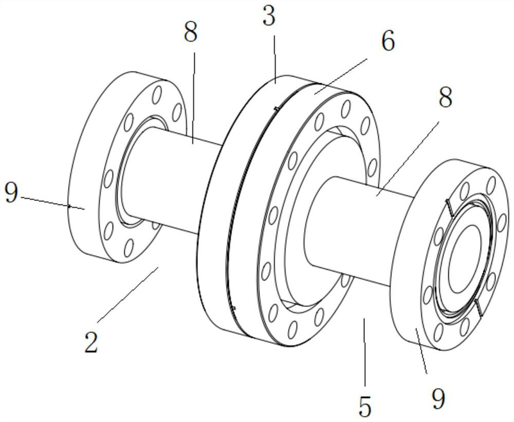
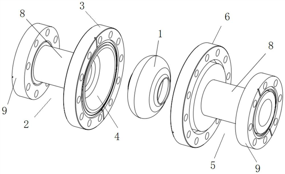
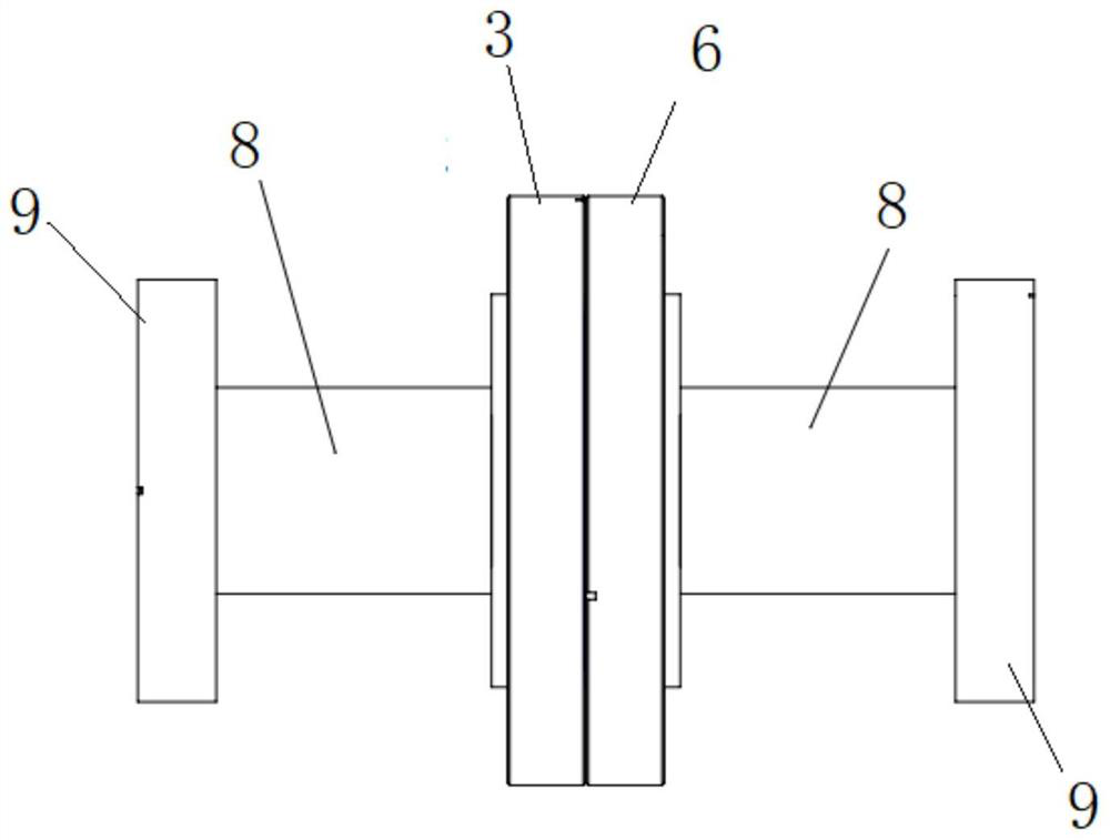
[0035] In this embodiment, a detachable nested composite superconducting cavity is provided. In this embodiment, as Figure 1 to Figure 7 shown, the nested composite superconducting cavity includes:

[0036] At least one superconducting inner cavity 1 is provided, and the superconducting inner cavity 1 is placed in a vacuum environment as a whole; since the superconducting inner cavity 1 is in a vacuum environment as a whole, its interior is a complete vacuum environment, and the outer wall is a vacuum environment, but it is in a vacuum environment. There is no atmospheric pressure difference between the inner and outer walls of the superconducting cavity 1.

[0037] The first non-superconducting shell 2 is provided with a first connection sealing flange 3 at one end, and a first semicircular groove 4 is provided on the inner side of the first connection sealing flange 3;

[0038] The second non-superconducting housing 5 is provided with a second connection sealing flange 6 ...

Embodiment 2

[0047] The disassembled nested composite superconducting cavity provided in this embodiment has basically the same structure as the disassembled nested composite superconducting cavity provided in Embodiment 1, the difference is that the superconducting cavity in this embodiment The number of inner cavities 1 is set to be two or more. In addition to the structure included in Embodiment 1, it also includes at least one double-headed housing 10, such as Figure 8 to Figure 11 shown.

[0048] The double-headed housing 10 is used as a connecting head, and both ends of the double-headed housing 10 are respectively provided with third connecting sealing flanges 11 , the inner side of the third connecting sealing flange 11 is provided with a third semicircular groove 12 , The grooves 12 are respectively matched with the first semicircular groove 4 and the second semicircular groove 7 to form sealed accommodating cavities respectively; each accommodating cavity is provided with a sup...


PUM


Abstract

The invention relates to a detachable nested composite superconductive cavity, which comprises at least one superconductive inner cavity, at least one heat exchanger, at least one heat exchanger, at least one heat exchanger, at least one heat exchanger, at least one heat exchanger and at least one heat exchanger, a first connection sealing flange is arranged at one end of the first non-superconducting shell, and a first semicircular groove is formed in the inner side of the first connection sealing flange; a second connection sealing flange is arranged at one end of the second non-superconducting shell, and a second semicircular groove is formed in the inner side of the second connection sealing flange; after the first connection sealing flange and the second connection sealing flange are installed in a matched mode, the first semicircular groove and the second semicircular groove are matched to form a sealed containing cavity, and the interior of the containing cavity is the vacuum environment used for containing the superconducting inner cavity. And the outer wall of the superconducting inner cavity is in contact with the inner wall of the accommodating cavity. The processing and processing difficulty of the superconducting cavity is greatly reduced, and the maintenance cost is also greatly reduced. The invention can be applied to the technical field of radio frequency superconducting.

Description

technical field [0001] The invention relates to the technical field of radio frequency superconductivity, in particular to a detachable nested composite superconducting cavity. Background technique [0002] The radio frequency superconducting cavity is a kind of electromagnetic resonant cavity. Compared with the normal conducting cavity, it has the advantages of high quality factor and high acceleration gradient. It is the core component of the particle accelerator. However, the superconducting materials used in it, such as metal niobium, cost Expensive and difficult to process. Also, the thermal conductivity of superconducting materials is generally low, and decreases with decreasing purity. At the same time, the interior of the superconducting cavity must be evacuated during testing and operation, and the exterior of the superconducting cavity sometimes needs to be placed in atmospheric pressure, and the cavity will withstand a high atmospheric pressure difference. In ord...

Claims


Application Information

Patent Timeline
IPC IPC(8): H05H7/20
CPCH05H7/20
Inventor 罗迪迪何源谭腾
Owner INST OF MODERN PHYSICS CHINESE ACADEMY OF SCI
Why Eureka
Try Eureka