Rack-mounted case contact heat dissipation module

A heat dissipation module and rack-type technology, applied in the field of contact heat dissipation modules of rack-type chassis, can solve the problems of increased energy consumption, small air specific heat capacity, and high system energy consumption, and achieve the effects of efficient heat dissipation and small temperature gradient

Pending Publication Date: 2022-07-05
南京吉左网络科技股份有限公司
View PDF0 Cites 0 Cited by
  • Summary
  • Abstract
  • Description
  • Claims
  • Application Information

AI Technical Summary

Problems solved by technology

As we all know, the specific heat capacity of air is small, and the heat transfer efficiency is low. Air exchange is used as the intermediate medium for heat dissipation. When the power of the equipment is large, it is necessary to use a "cold source" with a lower temperature and a larger air flow rate.
At this time, not only the energy consumption of the fan is high and the noise is loud, but the dust in the airflow can also easily cause the fan and heat sink to be blocked by dust, and the condensation of the low-temperature "cold source" surface cooler also increases the energy consumption, which makes the entire system consume more energy. , the failure rate is high; and the heat dissipation method of soaking the circuit board in the insulating and heat-conducting liquid is still in the experimental stage due to complicated technology, high cost, and polluting the environment. Cooling module

Method used


Image

  • Rack-mounted case contact heat dissipation module
  • Rack-mounted case contact heat dissipation module
  • Rack-mounted case contact heat dissipation module

Examples


Embodiment Construction

[0029] The technical solutions in the embodiments of the present invention will be clearly and completely described below with reference to the accompanying drawings in the embodiments of the present invention. Obviously, the described embodiments are only a part of the embodiments of the present invention, but not all of the embodiments.

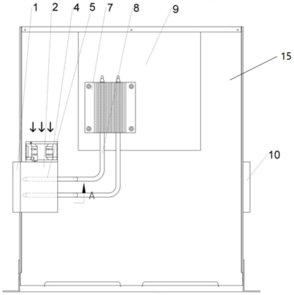
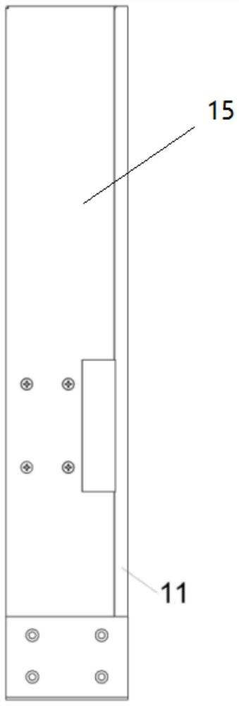
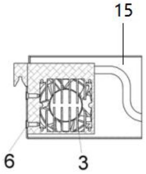
[0030] like Figure 1-7 As shown, a rack-type chassis contact heat dissipation module includes a chassis body 15. The chassis body 15 is provided with a heat conduction shoe 14, the heat conduction shoe 14 is in contact with a heat dissipation joint 1, and the heat dissipation joint 1 is welded with a module bracket 2. The module The bracket 2 is provided with a heat pipe socket 5, and the heat pipe socket 5 is provided with a heat-absorbing warping piece 3. The heat-absorbing warping piece 3 is detachably connected to the circulating fan 4 in the chassis through screw holes, and the heat dissipation joint 1 is fixed through the module fixin...


PUM


Abstract

The invention discloses a rack-mounted case contact heat dissipation module, and particularly relates to the field of computer heat dissipation, the rack-mounted case contact heat dissipation module comprises a case body, the case body is provided with a heat conduction shoe, the rack-mounted case contact heat dissipation module is made of a high-heat-conductivity material and is installed on a side plate of a case, and a heat dissipation connector faces the outside of the case; high-power heating components such as a CPU and a GPU in the case bodies are connected with the heat absorption fins through heat pipes, heat generated by other components is absorbed by the heat absorption fins through which air circulation in the case bodies passes, and when the case bodies are stacked on a rack, the heat dissipation connectors on the side faces of the case bodies are located in the same vertical space, so that the heat dissipation efficiency of the case bodies is improved. The vertical cold source pipeline is arranged on the side face of the machine frame, after the machine box body is horizontally inserted into the upper frame from the front portion of the machine frame, the heat dissipation connector is connected with the heat conduction shoe, efficient heat dissipation of electronic equipment can be achieved, and an efficient heat conduction channel independent of air exchange can be established between main high-power heating components in the machine box and a cold source outside the machine box through the design.

Description

technical field [0001] The invention relates to the field of computer heat dissipation, in particular to a rack-type chassis contact heat dissipation module. Background technique [0002] At present, with the rise of cloud computing, data centers of various scales have been built one after another. Because of the large number of devices and the high heat generation, the problem of heat dissipation has always plagued data center builders and operators. [0003] The network equipment chassis of the data center is basically a standard 19-inch rack-type structure, and these rack-type electronic equipment have high distribution density and high heat generation. The air inside and outside the chassis is exchanged for heat dissipation. In order to ensure the normal operation of the equipment, each data center basically adopts the method of first cooling the air, and then introducing the cold air into the electronic equipment chassis through the cabinet to dissipate the heat of the ...

Claims


Application Information

Patent Timeline
Patent Type & Authority Applications(China)
IPC IPC(8): H05K7/20
CPCH05K7/20709H05K7/20727H05K7/20809
Inventor 钟亚呋
Owner 南京吉左网络科技股份有限公司
Why Eureka
Try Eureka