Tab positioning method, tab processing system and storage medium

A positioning method and processing system technology, applied in metal processing, metal processing equipment, manufacturing tools, etc., can solve the problems of low lug spacing accuracy and large error, and achieve the effect of improving quality and accuracy

Pending Publication Date: 2022-07-08
SHENZHEN HYMSON LASER INTELLIGENT EQUIP CO LTD
View PDF0 Cites 2 Cited by
  • Summary
  • Abstract
  • Description
  • Claims
  • Application Information

AI Technical Summary

Problems solved by technology

[0006] In order to solve the defects of low precision and large error in the preset tab spacing in the prior art, the present invention proposes a tab positioning method, a tab processing system and a storage medium

Method used


Image

  • Tab positioning method, tab processing system and storage medium
  • Tab positioning method, tab processing system and storage medium
  • Tab positioning method, tab processing system and storage medium

Examples


Embodiment 1

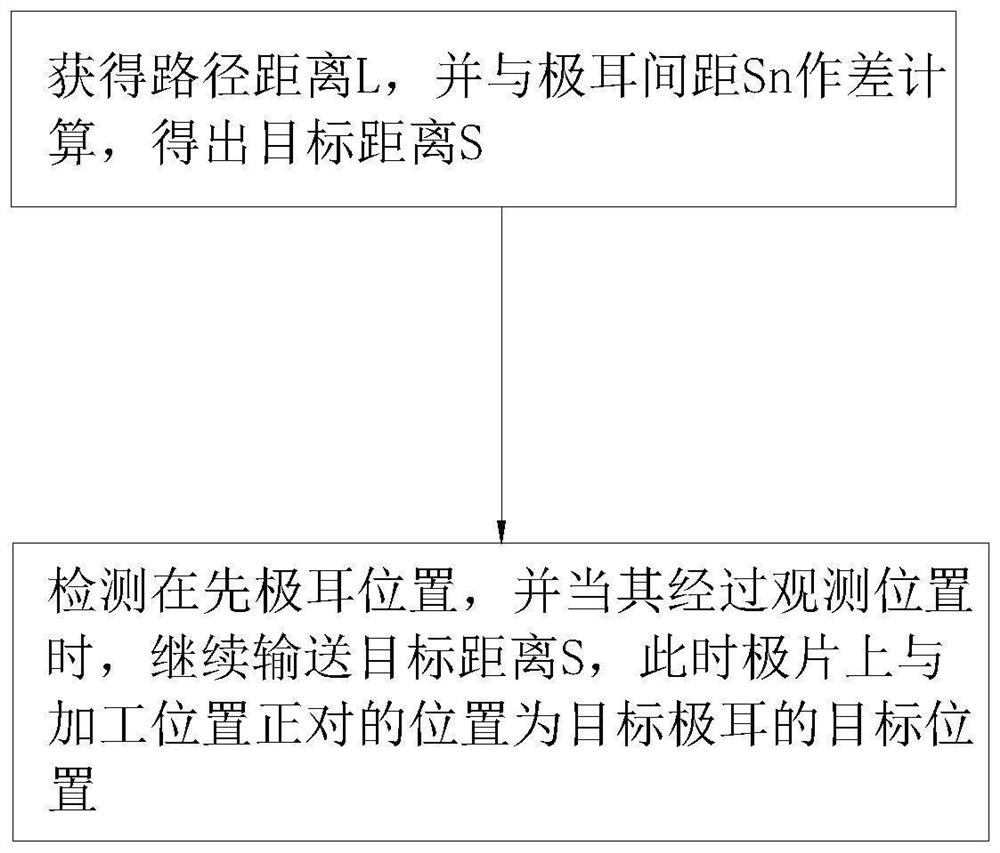
[0043] Embodiment 1: The pole ear positioning method is used to locate the pole ear position when the pole ear 2 is processed on the pole piece 1, such as figure 1 shown, including the following steps:

[0044] S1, obtain the path distance L from the tab processing position to the observation position, calculate the difference between the path distance L and the preset tab spacing Sn between two adjacent tabs, and obtain the target distance S, where S =Sn-L, S≥0;

[0045] S2, detect the position of the preceding pole tab, and continue to convey the preceding pole tab target distance S when the preceding pole tab passes the observation position, and at this time, the position on the pole piece corresponding to the processing position of the pole tab, Target position 3 for the target tab.

[0046] In this embodiment, when determining the target position 3 of the target tabs, it is based on the target distance S instead of the preset tab spacing Sn, and the target distance S is...

Embodiment 2

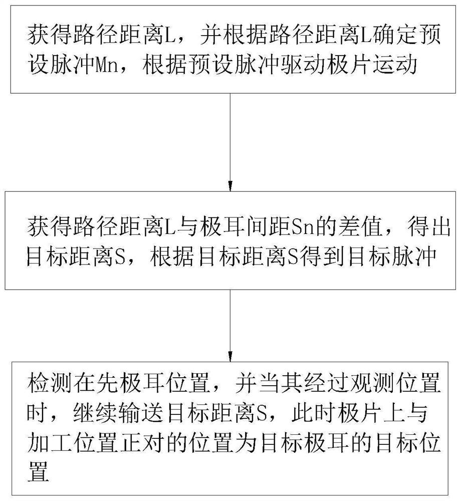
[0047] Embodiment 2: The pole ear positioning method is used to locate the position of the pole ear when the pole ear is processed on the pole piece, such as figure 2 shown, including the following steps:

[0048] S1, obtain the path distance L from the tab processing position to the observation position; calculate the difference between the path distance L and the preset tab spacing Sn between two adjacent tabs to obtain the target distance S, according to the The target distance S determines the target pulse signal, and according to the target pulse signal, the tab is transported from the observation position to the target distance S; where S=Sn-L, S≥0;

[0049] S2, detect the position of the preceding pole tab, and continue to convey the preceding pole tab target distance S when the preceding pole tab passes the observation position, and at this time, the position on the pole piece corresponding to the processing position of the pole tab, Target position 3 for the target ...

Embodiment 3

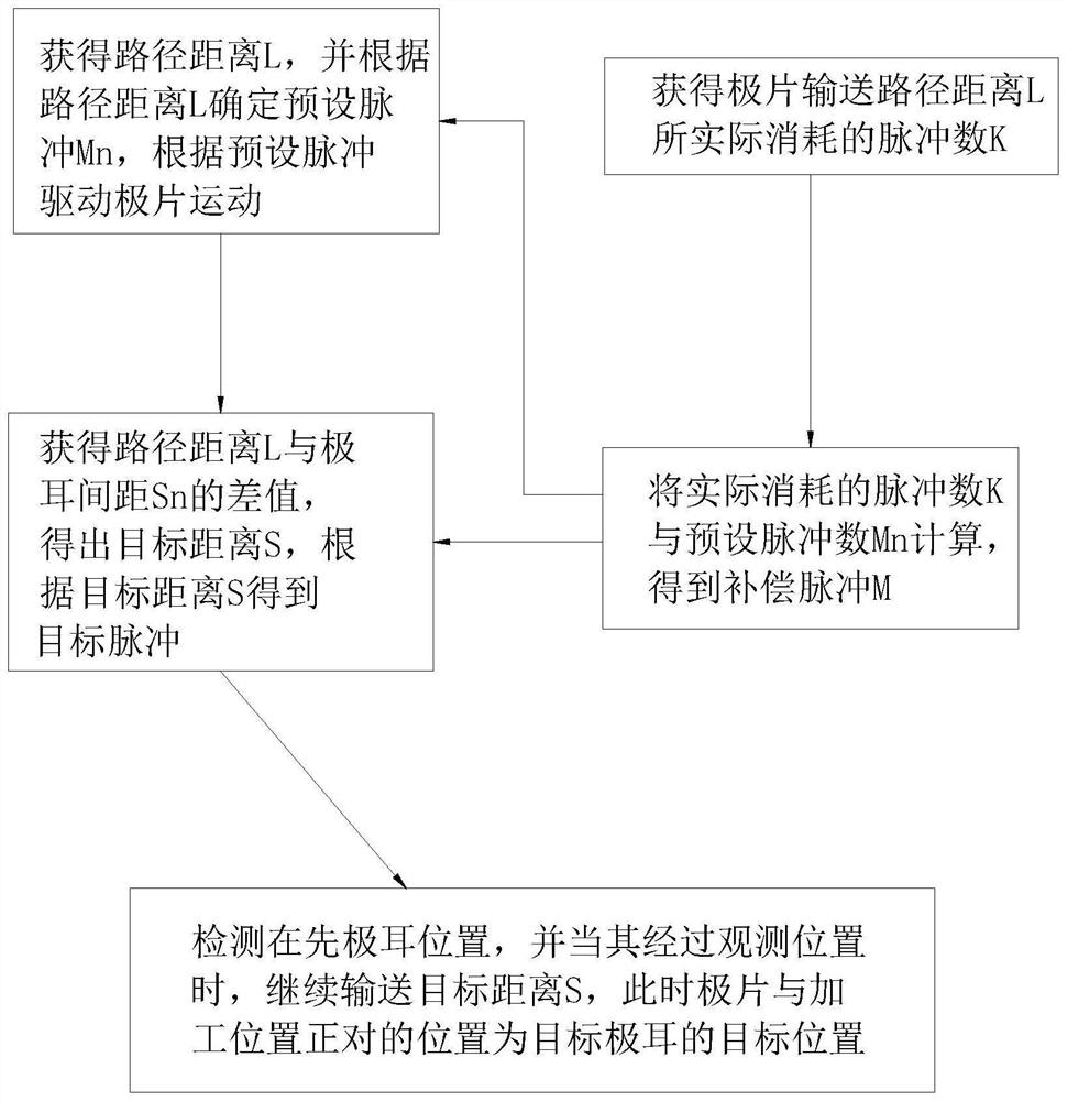
[0053] Embodiment 3: The pole ear positioning method, the difference from Embodiment 1 or 2 is that, such as image 3 It also includes: obtaining the actual pulse number K of the previous pole lug moving from the pole lug processing position to the observation position, and comparing and calculating with the preset preset pulse number Mn corresponding to the path distance L to obtain compensation The number of pulses M, and the target pulse signal is compensated and corrected according to the number of compensation pulses M, where M=Mn-K.

[0054] Specifically, performing compensation and correction on the target pulse signal refers to: performing compensation and correction on the preset pulse number Mn of the target tab; or, performing compensation and correction on the preset pulse number Mn of the next target tab; or , the compensation pulse number M of the next target tab is compensated and corrected; or, the preset pulse number Mn of the target tab and the next target ta...


PUM


Abstract

The invention discloses a tab positioning method, a tab processing system and a storage medium, and the method comprises the steps: obtaining a path distance L of a tab conveyed from a tab processing position to an observation position, calculating a difference value between the L and a preset tab distance Sn, and obtaining a target distance; and when the previous tab passes through the observation position, the previous tab is continuously conveyed by a target distance S, and at the moment, the position, corresponding to the tab processing position, on the pole piece is the position of the target tab. When the position of the target tab is determined, the target pulse signal is obtained according to the target distance S instead of the preset tab distance Sn, and the target distance S is far smaller than the preset tab distance Sn, so that the number of the target pulse signal is small, and the position of the target tab is determined. And the probability of slipping, pulse loss, jumping instability and the like in the execution process of a few pulse signals is low, so that the tab positioning precision is improved, a guarantee is provided for subsequent tab welding or cutting, and the final product quality is improved.

Description

technical field [0001] The invention relates to the technical field of laser processing, and in particular, to a pole ear positioning method, a pole ear processing system and a storage medium. Background technique [0002] Lithium battery products have high quality requirements, and one of the important parameters is the preset tab spacing accuracy of the battery pole pieces. However, how to improve the preset tab spacing accuracy has always been a difficult problem in the industry. [0003] The common method of controlling the cutting distance of the pole lug is mainly to determine the advancing distance of the pole piece by the number of pulses of the driving motor, that is, to set the number of pulses, and then use the encoder to convert the rotation angle, angular velocity and angular acceleration, as well as the roller diameter of the conveying roller. The parameter information such as size is fed back to the control system, so as to calculate the moving distance of the...

Claims


Application Information

Patent Timeline
Patent Type & Authority Applications(China)
IPC IPC(8): B23K26/38B23K26/70H01M50/531B23K101/36
CPCB23K26/38B23K26/702H01M50/531B23K2101/36Y02E60/10
Inventor 蒋志东宁森洪张松岭梁辰谢珩江桦锐邓剑杰吴磊胡传琦朱文宇
Owner SHENZHEN HYMSON LASER INTELLIGENT EQUIP CO LTD
Why Eureka
Try Eureka