Yarn feeding mechanism and spinning equipment thereof
A thread feeding and ironing technology, applied in the field of textile processing, can solve the problems of low practicability, single function, complex structure, etc., and achieve the effects of prolonging service life, avoiding uneven heat, and avoiding power consumption
- Summary
- Abstract
- Description
- Claims
- Application Information
AI Technical Summary
Problems solved by technology
Method used
Image

Examples
Embodiment 1
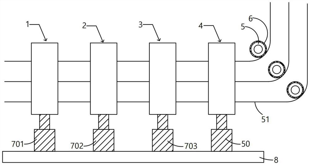
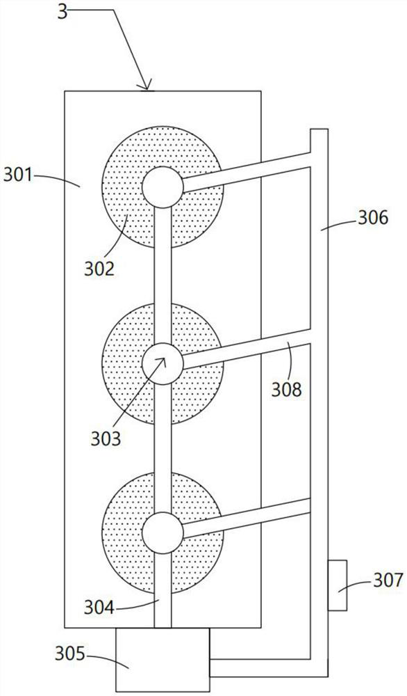
[0054] When in use, the spinning thread 51 can be cleaned, dyed and protected, dried and ironed according to actual needs. The contamination of the thread 51 will affect the quality of the subsequent finished product, and the spinning thread 51 can be wetted to make it shrink in advance after drying, so that the actual size of the finished product is more in line with the processing requirements. The dyeing agent is used for dyeing the spinning thread 51 that needs to change color. This dyeing is more flexible and more suitable for the temporary dyeing of a certain section of spinning thread 51 with special requirements. To make the treated yarn 51 more tough, beautiful, etc., the main function of the drying device 3 is to dry the yarn 51, so that the yarn 51 can be in a shrunk state, which is convenient for the setting of subsequent products.
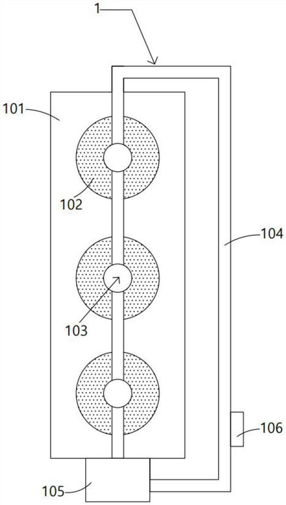
[0055]If all are required, the spinning thread 51 can be passed through the thread hole 103 in the cleaning device 1, the thread hole...
Embodiment 2
[0057] In the process of ironing the spinning thread 51, the rotary motor 44 can be started, and the rotary motor 44 drives the cam 46 to rotate continuously through the central shaft 45, so that the cam 46 pushes the sliding plate 12 intermittently, thereby making the heating roller 15 in the horizontal direction Moving back and forth, it should be noted that the horizontal movement range here is within a reasonable range, so the spinning thread 51 will not slide into the cutting groove 151; in addition, during the movement of the sliding plate 12, the gear 35 slides along the rack 36 Therefore, the gear 35 will rotate continuously, the gear 35 is fixedly connected with the driving bevel gear 37 through the rotating shaft 34, and the rotating shaft 34 is hingedly penetrated through the extension rod 33, so the driving bevel gear 37 can be driven to rotate, and the driving bevel gear 37 is driven by the driving bevel gear 37. The driven bevel gear 38 on the side rotates, the dr...
Embodiment 3
[0059] When the spinning thread 51 needs to be cut off, the cam 46 and the gear 35 can be used to make the cutting groove 151 on the heating roller 15 rotate to a proper position, and then the two fourth cylinders 50 can be adjusted independently so that the heating roller 15 can be adjusted to In the inclined state, the spinning thread 51 slides into the cutting groove 151. At this time, the cam 46 continues to push the sliding plate 12 outward, so that the spinning thread 51 exerts pressure on the pressing plate 22. The trigger rod 24 extends into the installation slot 152 until the heating switch 25 is in contact with the battery 27. When the heating switch 25 is energized at this time, the heating of the heating roller 15 will be controlled to be turned off, avoiding useless power consumption and saving energy; on the other hand, The spinning thread 51 continues to press down the pressing plate 22, so that the pressing plate 22 further pushes the first piston plate 17 throu...
PUM
 Abstract
Description
Claims
Application Information