Tunnel composite supporting structure for controlling rock creep effect and construction method thereof

A technology of creep effect and composite support, which is applied in the direction of tunnel, tunnel lining, climate change adaptation, etc., can solve the problems that the strength of the bolt body cannot be effectively utilized, the effect of controlling the deformation of the rock mass is poor, and the overall stability of the tunnel is affected. , to facilitate construction, improve labor efficiency, and facilitate assembly

Pending Publication Date: 2022-07-08
赵立财
View PDF0 Cites 0 Cited by
  • Summary
  • Abstract
  • Description
  • Claims
  • Application Information

AI Technical Summary

Problems solved by technology

[0004] The purpose of the present invention is to solve the problem that the existing initial support structure cannot effectively spread the load, reduce the load concentration, and cause the creep of the sandstone layer to cause local damage to the support structure, thereby affecting the overall stability of the tunnel. Grouting bolts provide insufficient anchoring force, the strength of the bolt body cannot be effectively utilized, and they are distributed in isolation, not connected into a whole, and the effect of controlling rock mass deformation is poor. The proposed tunnel composite method for controlling rock creep effect Support structure and its construction method

Method used


Image

  • Tunnel composite supporting structure for controlling rock creep effect and construction method thereof
  • Tunnel composite supporting structure for controlling rock creep effect and construction method thereof
  • Tunnel composite supporting structure for controlling rock creep effect and construction method thereof

Examples


Embodiment Construction

[0038] The technical solutions in the embodiments of the present invention will be clearly and completely described below with reference to the accompanying drawings in the embodiments of the present invention. Obviously, the described embodiments are only a part of the embodiments of the present invention, but not all of the embodiments. Based on the embodiments of the present invention, all other embodiments obtained by those of ordinary skill in the art without creative efforts shall fall within the protection scope of the present invention.

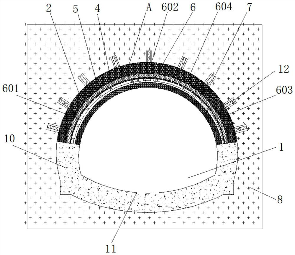
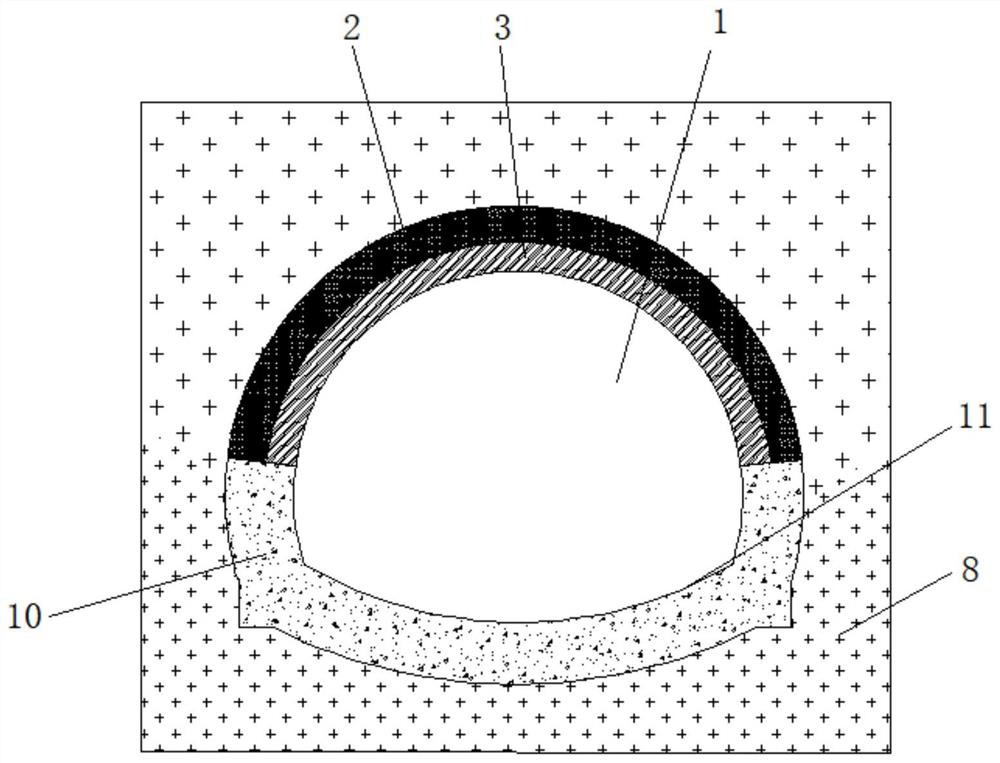
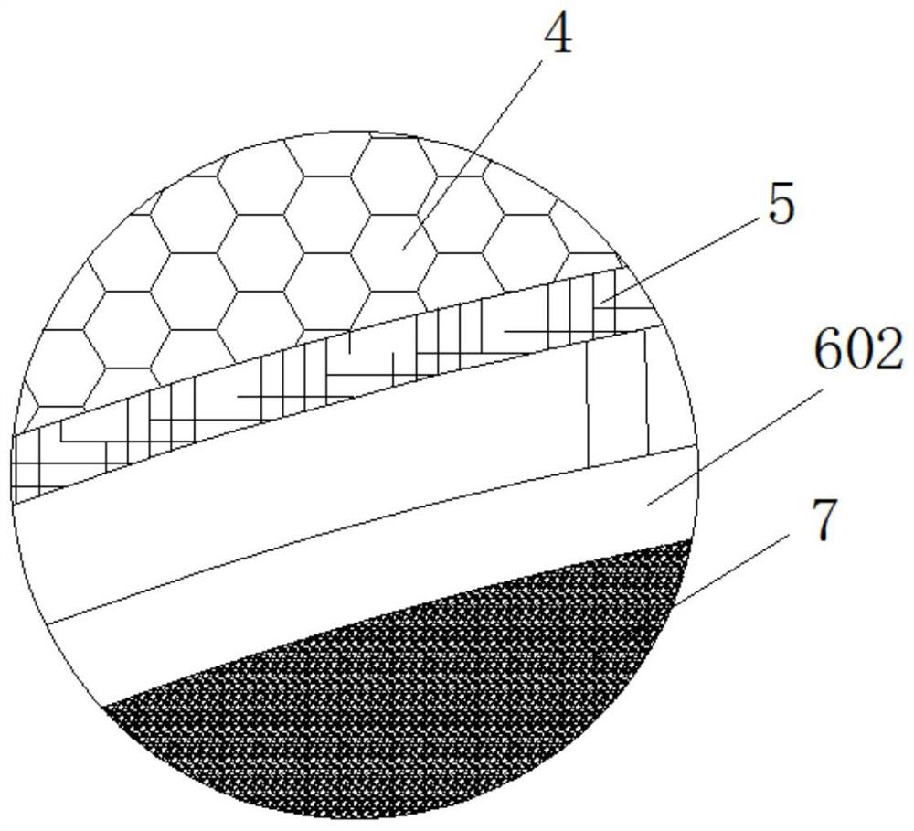
[0039] refer to Figure 1-11 , the tunnel composite support structure of controlling rock creep effect, comprises rock 8, is provided with tunnel 1 in rock 8, and the bottom of tunnel 1 is poured with inverted arch lining 11, and both sides of inverted arch lining 11 are provided with side wall foundation 10 , the upper end of the tunnel 1 is provided with a compressible foam concrete layer 2, the compressible foam concrete layer 2 is...


PUM


Abstract

The tunnel composite supporting structure for controlling the rock creep effect comprises rock, a tunnel is formed in the rock, an inverted arch lining is poured at the bottom of the tunnel, side wall foundations are arranged on the two sides of the inverted arch lining, a compressible foam concrete layer is arranged at the upper end of the tunnel, and the compressible foam concrete layer is arranged at the lower end of the tunnel. The compressible foam concrete layer is of an arch-shaped structure, the compressible foam concrete layer is jetted to the top end in the tunnel, a plurality of drill holes are annularly formed in the compressible foam concrete layer at equal intervals, hole walls are arranged in the drill holes, the drill holes extend into rock, combined type pre-stressed anchor rods are arranged in the drill holes, and the combined type pre-stressed anchor rods are arranged in the drill holes. The combined type pre-stressed anchor rod comprises an anchor rod body. According to the tunnel composite supporting structure for controlling the rock creep effect and the construction method of the tunnel composite supporting structure, through cooperative use of the anchoring combined type pre-stressed anchor rods and the compressible foam concrete layer, long-term elastic-plastic deformation of sandstone is controlled, the creep deformation speed of the sandstone is slowed down, and the deformation resistance of surrounding rock is enhanced.

Description

technical field [0001] The invention belongs to the field of tunnel construction, in particular to a tunnel composite supporting structure for controlling rock creep effect and a construction method thereof. Background technique [0002] Highway is an important lifeline of the national economy. Due to its unique flexibility and superiority, it plays an irreplaceable role in other modes of transportation. Highway tunnels are one of the important components of highway engineering structures. With the development of our country, the western development strategy The implementation of high-grade highways has extended from the coastal areas to the southwest and northwest mountainous areas, and the construction scale of highway tunnels has become larger and larger. The original two-lane tunnel is far from being able to meet the increasing traffic requirements. Correspondingly complex, in the environment of extremely high in-situ stress and soft rock, due to the combined action of h...

Claims


Application Information

Patent Timeline
Patent Type & Authority Applications(China)
IPC IPC(8): E21D11/10E21D11/18E21D11/38E21D20/02
CPCE21D11/105E21D11/183E21D11/381E21D11/383E21D20/021Y02E10/20
Inventor 赵立财
Owner 赵立财
Why Eureka
Try Eureka