Print head and workpiece plane position calibration method
A technology of plane position and print head, which is applied in the field of calibration of print head and workpiece plane position, can solve problems such as low calibration efficiency and complicated calibration methods, and achieve the effect of improving efficiency, improving calibration efficiency, and improving positioning accuracy
- Summary
- Abstract
- Description
- Claims
- Application Information
AI Technical Summary
Problems solved by technology
Method used
Image

Examples
Embodiment 1
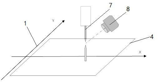
[0051] The 3D printing equipment suitable for this position calibration method includes a two-dimensional drive platform 1 that can move in the XY direction, a bracket 2 that can move in the Z direction, and a calibration silicon wafer 3. The workpiece plane 4 is installed on the two-dimensional drive platform 1. A laser altimetry sensor 5 , a vertical industrial camera 6 , and an inclined industrial camera 8 are installed on the bracket 2 , and a lens is installed on the vertical industrial camera 6 to facilitate the vertical industrial camera 6 to focus on the product.
[0052] The method for calibrating the plane position of the print head and the workpiece includes the following steps:
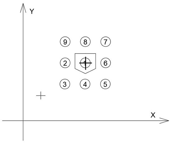
[0053] (S1) The print head forms a print point on the workpiece plane, and the positional relationship between the print head and the camera cross center is calibrated according to the print point;
[0054] (S2) Setting a datum point on the workpiece plane, calibrating the positional relat...
Embodiment 2
[0081] This embodiment replaces the manual calibration step of step ( S1 ) in the first embodiment, and the rest of the calibration methods are consistent with the first embodiment.
[0082] The automatic calibration steps of step (S1) are as follows,
[0083] (1.1b) The print head discharges the material to form a print point on the workpiece plane, and the pixel position coordinates of the print point are (X1, Y1);
[0084] (1.2b) The equipment automatically drives the workpiece plane to move, the equipment automatically records the moving distance, and moves the printing point on the workpiece plane into the camera's field of view;
[0085] (1.3b) Calculate the distance between the print point in the camera's field of view and the center of the camera;
[0086] (1.4b) According to the distance obtained in step (1.3b) and the moving distance of the workpiece plane in step (1.2b), calibrate the positional relationship between the center of the camera and the print head.
[...
Embodiment 3
[0089] This embodiment replaces the automatic calibration step of step ( S3 ) in the first embodiment, and the rest of the calibration methods are consistent with the first embodiment.
[0090] The automatic calibration steps of step (S3) are as follows,
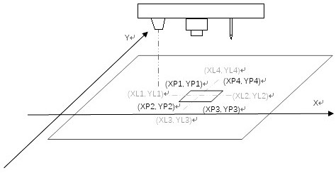
[0091] (3.1a) The printing needle discharges the material, drives the workpiece plane to move, and prints a rectangular wireframe on the workpiece plane. The rectangular wireframe forms four vertex coordinates (XP1, YP1) (XP2, YP2) (XP3, YP3) ( XP4, YP4);
[0092] (3.2a) After the printing is completed, drive the workpiece plane to move linearly along the X and Y directions;
[0093] (3.3a) During the movement, record the coordinate information of the laser sensor measuring the height at the maximum value, that is, the intersection of the laser sensor and the rectangular wire frame during the movement, and the coordinates of the intersection are (XL1, YL1) (XL2, YL2) (XL3 , YL3) (XL4, YL4);
[0094] (3.4a) Calculate the m...
PUM
 Abstract
Description
Claims
Application Information
 - R&D
- Intellectual Property
- Life Sciences
- Materials
- Tech Scout
- Unparalleled Data Quality
- Higher Quality Content
- 60% Fewer Hallucinations
Browse by: Latest US Patents, China's latest patents, Technical Efficacy Thesaurus, Application Domain, Technology Topic, Popular Technical Reports.
© 2025 PatSnap. All rights reserved.Legal|Privacy policy|Modern Slavery Act Transparency Statement|Sitemap|About US| Contact US: help@patsnap.com