
Plasma density control system and method

A plasma and density control technology, applied in circuits, discharge tubes, electrical components, etc., can solve problems such as reducing production costs and uneven etching, and achieve the effect of reducing production costs and solving uneven etching problems.

Pending Publication Date: 2022-07-08
JIANGSU LEUVEN INSTR CO LTD
View PDF0 Cites 0 Cited by
  • Summary
  • Abstract
  • Description
  • Claims
  • Application Information

AI Technical Summary

Problems solved by technology

[0006] The technical problem to be solved by the present invention is to provide a plasma density control system for the above-mentioned deficiencies in the prior art. The plasma density control system and method can measure the ion beam density drawn from the ion source, and control the Density is controlled in real time, effectively solving the problem of uneven etching caused by changes in process conditions, and reducing production costs

Method used

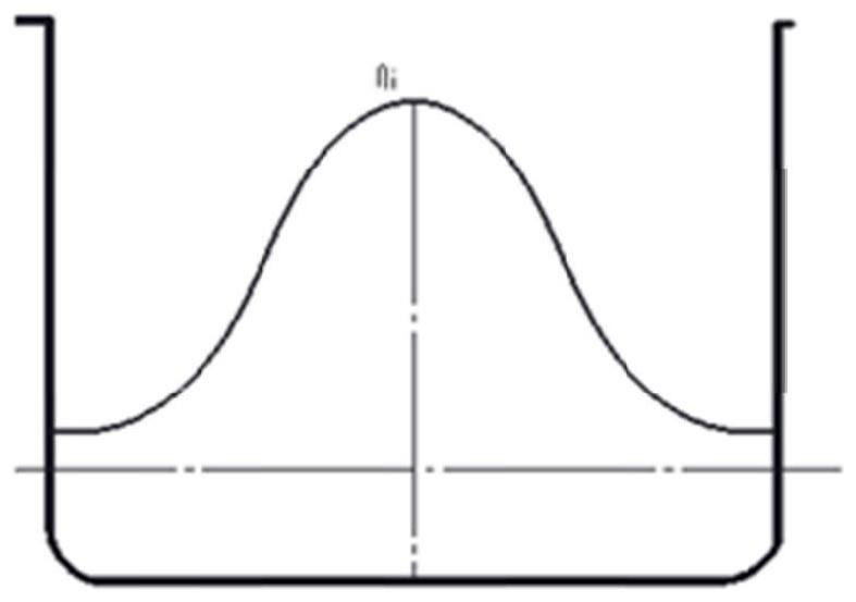
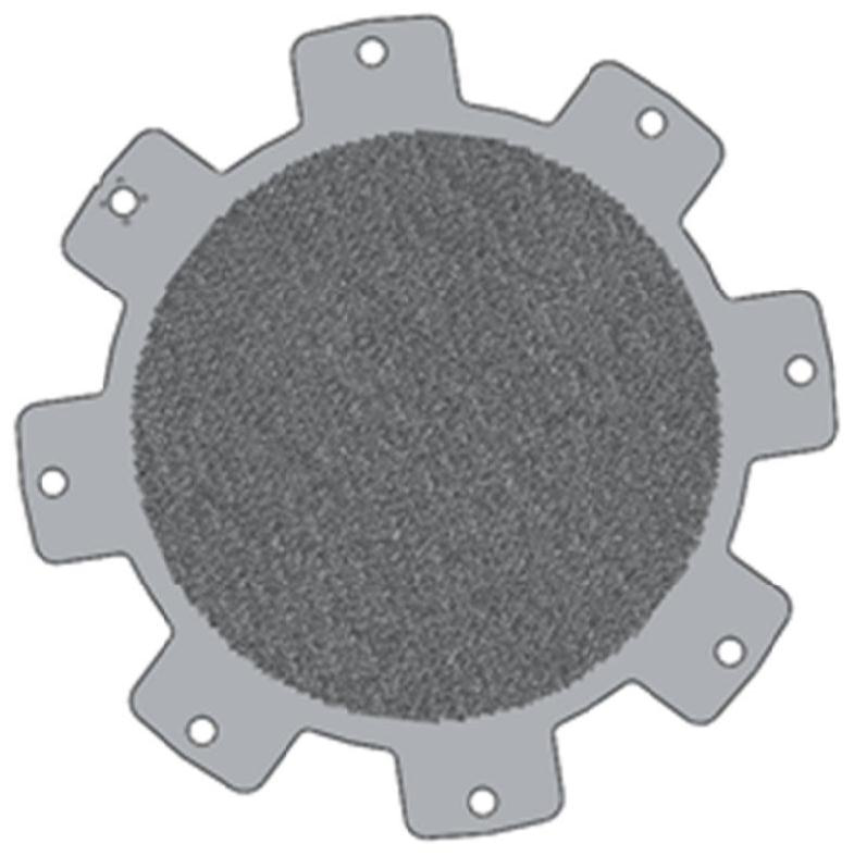
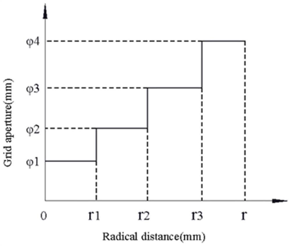

Image

  • Plasma density control system and method
  • Plasma density control system and method
  • Plasma density control system and method

Examples


Embodiment 1

[0074] Example 1 The Faraday cup mounting frame is a straight bar frame

[0075] The Faraday cup mounting rack is a straight rack, and the number of Faraday cups is N+1. In this embodiment, since there are six groups of annular holes in the screen grid, that is, N=6, the number of Faraday cups is seven, such as Figure 8 As shown, from the center to the outside are Faraday Cup 1, Faraday Cup 2, Faraday Cup 3, Faraday Cup 4, Faraday Cup 5, Faraday Cup 6 and Faraday Cup 7.

[0076] One of the Faraday cups (that is, Faraday cup 1) is located on the central axis of the reaction chamber, and the remaining N Faraday cups are collinearly installed on the straight rack and correspond to the positions of the N screen grid annular holes.

[0077] That is, Faraday cup 2, Faraday cup 3, Faraday cup 4, Faraday cup 5, Faraday cup 6 and Faraday cup 7 are respectively 2.35mm, 2.47mm, 2.63mm, 2.72mm, 2.91mm and 3.13mm screen grid annular holes Accordingly, it is ensured that the plasma densi...

Embodiment 2

[0079] like Figure 9 As shown, the Faraday cup mount has an L-shaped frame (which can be a cross) with the corners of the L-shaped frame located on the central axis of the reaction chamber. The number of Faraday cups is preferably 2N+1.

[0080] One of the Faraday cups (that is, Faraday cup 1) is installed on the corner of the L-shaped frame, and N Faraday cups are installed on each of the two right-angled sides of the L-shaped frame.

[0081] The N Faraday cups on one of the right-angled sides are Faraday Cup 2, Faraday Cup 3, Faraday Cup 4, Faraday Cup 5, Faraday Cup 6, and Faraday Cup 7.

[0082] The N Faraday cups on the other right-angled side are Faraday cup 8, Faraday cup 9, Faraday cup 10, Faraday cup 11, Faraday cup 12, and Faraday cup 13.

[0083] 2N Faraday cups are located at different radial positions of the screen grid, and are respectively corresponding to the positions of the N screen grid annular holes. That is, Faraday cup 2 and Faraday cup 8 correspond t...


PUM


Abstract

The invention discloses a plasma density control system and method. The plasma density control system comprises an ion source, a reaction chamber, a separation blade mechanism and a Faraday cup group, the Faraday cup group is arranged on the wall surface of the reaction chamber corresponding to the screen grid and comprises a Faraday cup mounting rack and at least N Faraday cups; the N Faraday cups correspond to the N groups of screen grid annular holes in the screen grid in position; the separation blade mechanism comprises a driving device controller and at least two groups of separation blade assemblies; each group of separation blade assembly comprises a plurality of separation blades and a separation blade driving device; the plurality of separation blades are uniformly distributed along the circumferential direction of the tail end of the discharge cavity; each separation blade can rotationally extend into the discharge cavity to shield the plasma entering the annular hole of the screen grid; the blocking pieces between the blocking piece assemblies are alternately arranged, and the blocking pieces between the blocking piece assemblies are different in shape. According to the invention, the density of the ion beam led out by the ion source can be measured, the plasma density can be controlled in real time, the problem of non-uniform etching caused by change of process conditions is effectively solved, and the production cost is reduced.

Description

technical field [0001] The invention relates to the field of ion beam etching, in particular to a plasma density control system and method. Background technique [0002] Ion beam etching can be used to etch various metals (Ni, Cu, Au, Al, Pb, Pt, Ti, etc.) and their alloys, as well as non-metals, oxides, nitrides, carbides, semiconductors, polymers , ceramics, infrared and superconducting materials. In principle, the argon gas is decomposed into argon ions by the principle of glow discharge, and the argon ions are accelerated by the anode electric field to physically bombard the surface of the sample to achieve the effect of etching. In the etching process, Ar gas is charged into the discharge chamber of the ion source and ionized to form a plasma, and then the ions are extracted and accelerated by the grid, and the ion beam with a certain energy enters the working chamber and shoots towards the solid surface to bombard the solid. Surface atoms make material atoms sputter ...

Claims


Application Information

Patent Timeline
Patent Type & Authority Applications(China)
IPC IPC(8): H01J37/32H01J37/08
CPCH01J37/32449H01J37/32633H01J37/32651H01J37/08H01J37/32H01J37/09H01J37/3053
Inventor 胡冬冬张瑶瑶刘小波张怀东刘海洋李娜郭颂李晓磊许开东
Owner JIANGSU LEUVEN INSTR CO LTD
Learn More