
Eureka
For R&D, Eureka makes reading and utilizing patents & technical documents easy.
Eureka AIR
Designed for self-driven R&D workflows. Generate viable solutions, solve complex R&D challenges, empower your innovation with AI.

Eureka Materials
Designed for material experts only. Revolutionize your material R&D, from search, analyze, to developing new materials.

TechResearch
Generate reliable direction feasibility study reports for your R&D in just a few steps.

TechSeek
Discover and master advanced knowledge NOW. Basics, ideas, possibilities, all at once.

TechMind
As an expert in R&D Theories, TechMind can generates customized viable solutions instantly.

TechRisk
Analyze your overall solution with one click, know your potential R&D risks in advance.

TechMonitor
Get weekly tech updates, stay abreast of the latest tech innovations and key insights.
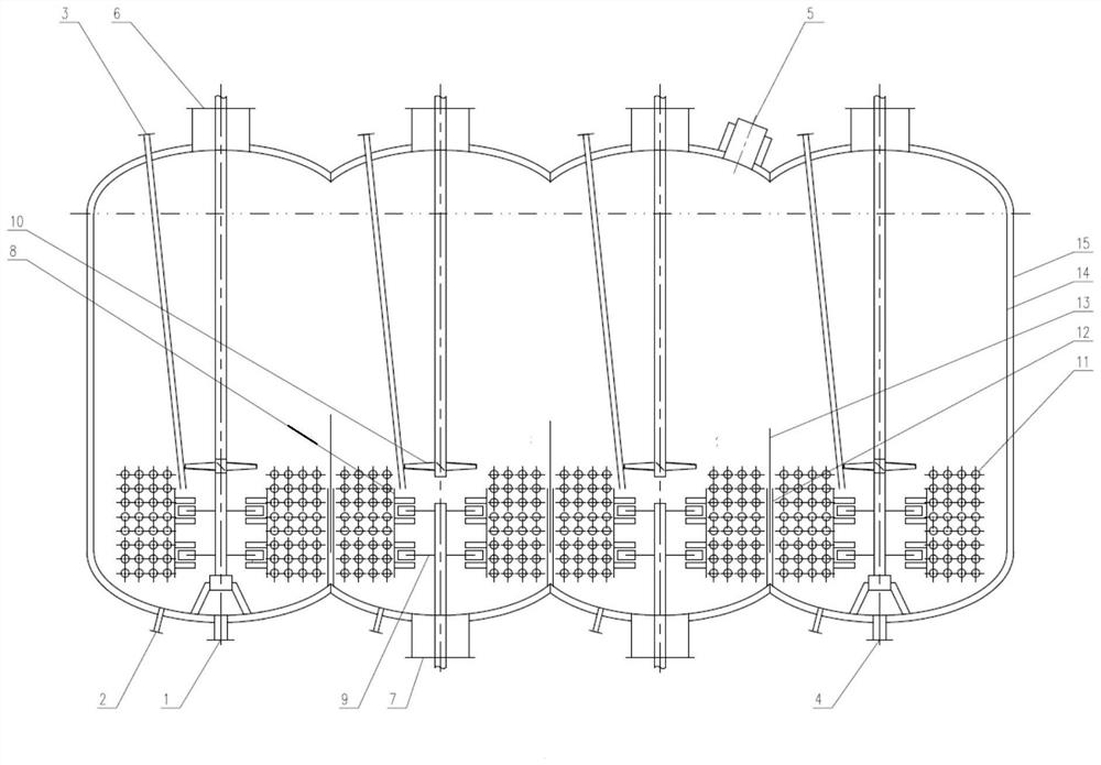
Continuous reaction kettle
A reaction kettle and reaction technology, applied in chemical/physical/physical-chemical stationary reactors, chemical/physical/physical-chemical processes, chemical instruments and methods, etc., can solve problems such as re-agglomeration of functional powders, and achieve simplified control method, the effect of improving control efficiency
- Summary
- Abstract
- Description
- Claims
- Application Information
AI Technical Summary
Problems solved by technology
Method used
Image

Examples
Embodiment 1
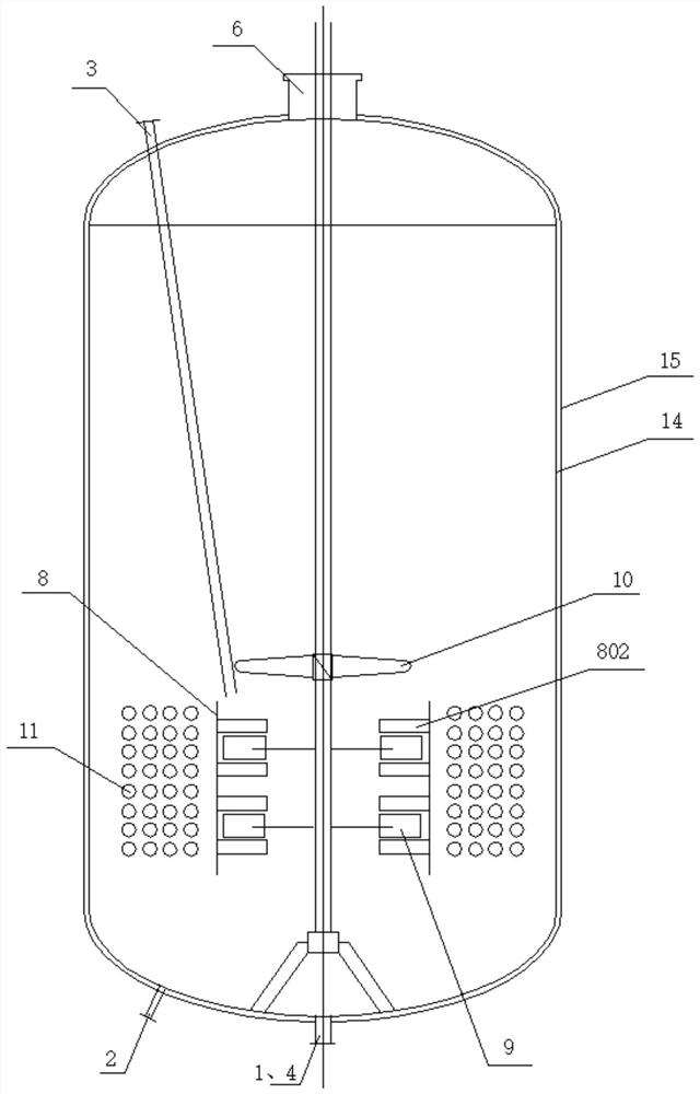
[0051] As an embodiment of the present invention, this embodiment provides a high shear reactor, such as figure 1 As shown, there is a reaction chamber inside the high shear reaction kettle, and a shear jet device is arranged in the reaction chamber, including,
[0052]A radial flow stirring paddle, located inside the reaction chamber, has a rotating shaft and a paddle, and is used to drive the reactants to flow in the radial direction;
[0053] a shear jet mechanism, located inside the reaction chamber, fixedly connected with the inner wall of the reaction chamber, and has a cavity for accommodating the radial flow stirring paddle;
[0054] The radial flow stirring paddle is located in the shear jet mechanism, which provides power for the reactants in the cavity, so that the reactants are sprayed to the outside through the shear jet mechanism, which realizes the full dispersion of the functional powder in the reactants and avoids the function of Agglomeration of powders.
...
Embodiment 2
[0064] As another embodiment of the present invention, this embodiment is further improved on the basis of Embodiment 1, and the details are as follows.
[0065] like Figure 4 and Figure 5 As shown, in this embodiment, the high shear reactor also includes,
[0066] The baffle 802 is fixed on the guide tube 8 and extends inward from the inner wall of the guide tube 8 .
[0067] The baffle 802 is located on one side of the paddle along the axial direction of the guide tube 8, and is fixedly connected with the inner wall of the guide tube 8.
[0068] Specifically, the plane where the baffle plate 802 is located is parallel to the axis of the guide tube 8 , and the length along the radial direction of the guide tube 8 is greater than the gap between the guide tube 8 and the end of the blade , the radial flow stirring paddle 9 drives the reactant to move in the circumferential direction of the diversion cylinder 8 during the rotation process. When passing through the baffle 80...
Embodiment 3
[0074] As another embodiment of the present invention, the embodiment of this city makes further improvements on the basis of the second embodiment, and the details are as follows.
[0075] In this embodiment, the radial flow stirring paddle 9 and the guide cylinder 8 are located at the lower part of the reactor, and an axial flow stirring paddle for guiding the reactants to flow along the axial direction to the radial flow stirring paddle 9 is also provided in the reactor. 10, the axial flow stirring paddle 10 can be arranged above or below the radial flow stirring paddle 9; the above-mentioned scheme is formed in the reactor by the radial flow stirring paddle 9, the guide cylinder 8 and the axial flow stirring paddle 10 for the circulation of the reactants. The passage of the duct, so that the reactants located outside the diversion cylinder 8 can be continuously supplemented into the interior of the diversion cylinder 8, thereby realizing the full dispersion of the functiona...
PUM
 Abstract
Description
Claims
Application Information
 - R&D Engineer
- R&D Manager
- IP Professional
- Industry Leading Data Capabilities
- Powerful AI technology
- Patent DNA Extraction
Browse by: Latest US Patents, China's latest patents, Technical Efficacy Thesaurus, Application Domain, Technology Topic, Popular Technical Reports.
© 2024 PatSnap. All rights reserved.Legal|Privacy policy|Modern Slavery Act Transparency Statement|Sitemap|About US| Contact US: help@patsnap.com