Voltage reduction power supply circuit structure and voltage reduction power supply
A step-down power supply and circuit structure technology, which is applied in the direction of high-efficiency power electronic conversion, electrical components, and adjustment of electrical variables, etc. It can solve the problem that the upper bridge arm switch tube cannot be set to 100% duty cycle, and the bootstrap capacitor cannot be bootstrapped and charged. problems, to achieve the effect of reducing the pressure drop
- Summary
- Abstract
- Description
- Claims
- Application Information
AI Technical Summary
Problems solved by technology
Method used
Image
Examples
Embodiment 1
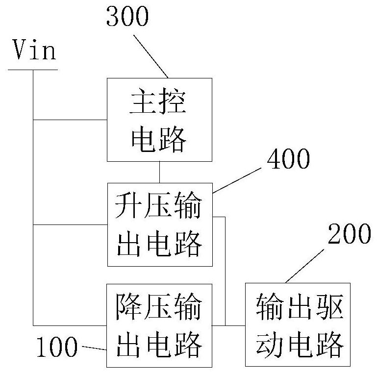
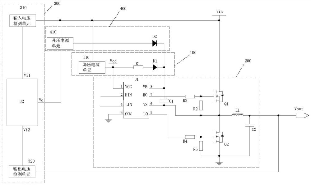
[0044] In some alternative embodiments, such as Figure 2 to Figure 3 As shown, the present application provides a step-down power supply circuit structure, including a step-down output circuit 100 , an output driving circuit 200 , a main control circuit 300 and a step-up output circuit 400 . The step-down output circuit 100 is connected to the circuit input terminal Vin, and the step-down output circuit 100 is used to receive the voltage signal of the circuit input terminal Vin and output the first voltage signal after the step-down; the output drive circuit 200 and the step-down output circuit 100 The output terminal of the circuit 300 is connected to the circuit input terminal Vin, and receives the first voltage signal to charge the bootstrap capacitor C1 of the upper-arm switch tube Q1; the main control circuit 300 is connected to the circuit input terminal Vin, receives the voltage signal of the current input terminal Vin, and When the voltage signal of the circuit input ...
Embodiment 2
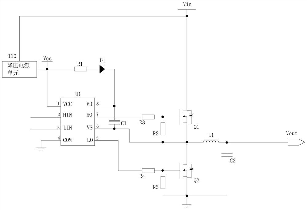
[0050] Optionally, the step-down output circuit 100 includes a step-down power supply unit 110, a first resistor R1 and a first diode D1;
[0051] The input terminal of the step-down power supply unit 110 is connected to the circuit input terminal Vin, and the output terminal of the step-down power supply unit 110 is connected to one end of the first resistor R1;
[0052] The other end of the first resistor R1 is connected to the anode of the first diode D1 , and the cathode of the first diode D1 is connected to the output driving circuit 200 .
[0053] Optionally, the output driving circuit 200 includes a driving chip U1, a second resistor R2, a third resistor R3, a fourth resistor R4, a fifth resistor R5, a bootstrap capacitor C1, a lower-arm switch Q2 and a lower-arm switch. Q1;
[0054] The driver chip U1 includes a chip voltage pin VCC, a first input pin HIN, a second input pin LIN, a first control pin VB, a second control pin VS, a first output pin HO, and a second outp...
Embodiment 3
[0088]In some optional embodiments, the present application further provides an electrical device, including the above-mentioned step-down power supply circuit structure.
[0089] During implementation, the structure of the step-down power supply circuit of the electrical equipment includes a step-down output circuit 100 , an output driving circuit 200 , a main control circuit 300 and a booster output circuit 400 . The step-down output circuit 100 is connected to the circuit input terminal Vin, and the step-down output circuit 100 is used to receive the voltage signal of the circuit input terminal Vin and output the first voltage signal after the step-down; the output drive circuit 200 and the step-down output circuit 100 The output terminal of the circuit 300 is connected to the circuit input terminal Vin, and receives the first voltage signal to charge the bootstrap capacitor C1 of the upper-arm switch tube Q1; the main control circuit 300 is connected to the circuit input te...
PUM
 Abstract
Description
Claims
Application Information
 - R&D
- Intellectual Property
- Life Sciences
- Materials
- Tech Scout
- Unparalleled Data Quality
- Higher Quality Content
- 60% Fewer Hallucinations
Browse by: Latest US Patents, China's latest patents, Technical Efficacy Thesaurus, Application Domain, Technology Topic, Popular Technical Reports.
© 2025 PatSnap. All rights reserved.Legal|Privacy policy|Modern Slavery Act Transparency Statement|Sitemap|About US| Contact US: help@patsnap.com


