Motor rotor welding tool assembly with positioning function
A technology of motor rotor and welding tooling, which is applied in the manufacture of stator/rotor body, welding equipment, auxiliary welding equipment, etc. It can solve the problems of inconvenient welding and inconvenient adjustment of motor rotor, and achieve the effect of easy welding
- Summary
- Abstract
- Description
- Claims
- Application Information
AI Technical Summary
Problems solved by technology
Method used
Image

Examples
Embodiment 1
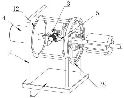
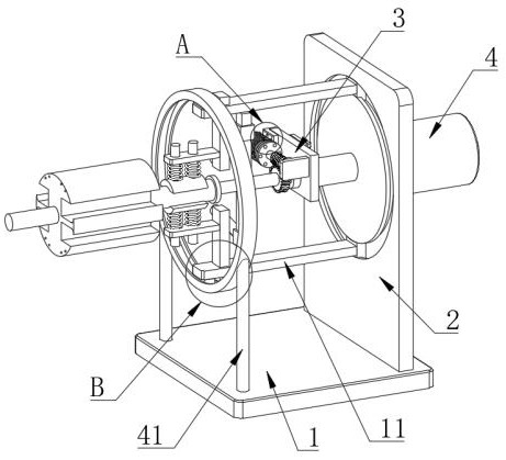
[0033] Example one, by Figure 1 to Figure 8 Given, the present invention includes a fixed base 1, the top of the fixed base 1 is fixedly connected with a side plate 2, one side of the side plate 2 is provided with a movable support seat 3, and the movable support seat 3 and the side plate 2 are connected by a hydraulic expansion piece 4, One side of the movable support base 3 is provided with a rotating shaft 5, one end of the rotating shaft 5 is connected with the movable support base 3 through the first bearing 6, the outer sleeve of the rotating shaft 5 is provided with a fixedly connected worm gear 7, and one side of the movable support base 3 is provided with The worm 8, one end of the worm 8 is connected with the movable support base 3 through a rotating member, the other end of the worm 8 is connected with the movable support base 3 through a welding rotary drive assembly, and one end of the rotating shaft 5 away from the movable support base 3 is provided with a weldin...
Embodiment 2
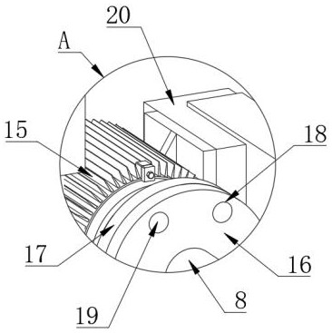
[0035] Embodiment 2, on the basis of Embodiment 1, by figure 1 , figure 2 , image 3 , Figure 7 and Figure 8 Given, the welding rotary drive assembly includes a motor 15 arranged on one side of the movable support base 3, one end of the worm 8 is fixedly connected with a first turntable 16, the output end of the motor 15 is provided with a second turntable 17, and one end of the first turntable 16 is provided. A plurality of insertion holes 18 are provided on the side, and a plurality of insertion rods 19 are fixedly connected to one side of the second turntable 17. The insertion rods 19 are located in the insertion holes 18, the motor 15 is fixedly connected to the mounting frame 20, and the movable support base 3 is provided with a card. Slot 21, a plug-in board 23 is fixedly connected to the mounting frame 20, a through hole 22 is opened on one side of the inner wall of the card slot 21, a limit hole 24 is set on one side of the plug-in board 23, and one side of the m...
Embodiment 3
[0037] Embodiment 3, on the basis of Embodiment 1, by figure 1 and Figure 5 Given, the rotating member includes a second fixing plate 29 arranged at one end of the worm 8, one side of the second fixing plate 29 is fixedly connected with one side of the movable support base 3, and one end of the worm 8 and the second fixing plate 29 pass through the second The bearing 30 is connected, and the rotating swing member includes a movable sleeve 31 arranged on one side of the movable adjustment plate 10, and the movable sleeve 31 is sleeved on the outside of the first fixed plate 9, and one side of the movable sleeve 31 is provided with a second connecting plate 32, Both ends of the second connecting plate 32 are rotatably connected with the movable sleeve 31 and the movable adjusting plate 10 respectively;
[0038] The motor rotor to be processed is placed between the two clamping plates 14 , and the hydraulic telescopic element 4 drives the movable support base 3 to move, so that...
PUM
 Abstract
Description
Claims
Application Information
 - R&D
- Intellectual Property
- Life Sciences
- Materials
- Tech Scout
- Unparalleled Data Quality
- Higher Quality Content
- 60% Fewer Hallucinations
Browse by: Latest US Patents, China's latest patents, Technical Efficacy Thesaurus, Application Domain, Technology Topic, Popular Technical Reports.
© 2025 PatSnap. All rights reserved.Legal|Privacy policy|Modern Slavery Act Transparency Statement|Sitemap|About US| Contact US: help@patsnap.com