Welding tool for automobile parts

A technology for welding tooling and auto parts, applied in applications, household appliances, household components, etc., can solve the problems of radar detection range deviation, wire drawing, etc., and achieve the effect of ensuring design accuracy, uniform heat, and uniform external heat dissipation

Active Publication Date: 2022-07-15
NANTONG INST OF TECH
View PDF32 Cites 0 Cited by
  • Summary
  • Abstract
  • Description
  • Claims
  • Application Information

AI Technical Summary

Problems solved by technology

[0003] However, during the long-term use, it is found that the existing welding tool still has certain disadvantages: 1. The orientation of the welding head of the puncture welding relative to the welding end faces of the front radar bracket and the corner radar bracket remains unchanged. Speed ​​welding processing, but because the welding end faces of the front radar bracket and the corner radar bracket are not full-plane sections, and the flat puncture welding welding head is in the welding process of the curved surface end of the weldment, even at the same welding point. There is a situation where one side does not completely pass through the weldment, resulting in a wire drawing phenomenon that does not penetrate through the fused plastic hole during the pulling process; 2. During the cooling process after welding, rebound deformation occurs between the weldment and the welding body. The relative angle between the front radar bracket and the corner radar bracket changes, resulting in a deviation in the detection range of the radar from the pre-designed after the corresponding radar is installed.

Method used


Image

  • Welding tool for automobile parts
  • Welding tool for automobile parts
  • Welding tool for automobile parts

Examples


Embodiment Construction

[0021] In order to make the technical means, creative features, achievement goals and effects realized by the present invention easy to understand, the present invention will be further described below with reference to the specific embodiments.

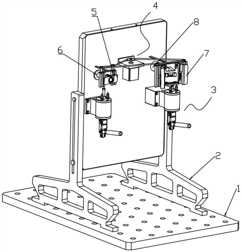
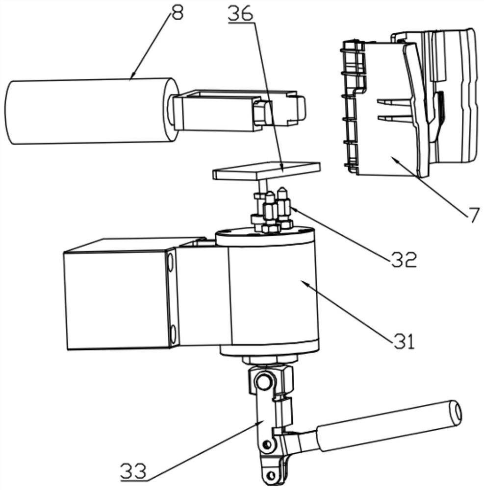
[0022] like Figure 1 to Figure 5 As shown, a welding tool for auto parts includes a base 1, an installation frame 2, a positioning mechanism 3 and a compensation mechanism 4. The installation frame 2 can be adjusted and installed on the base 1. Placement seat one 6 of the radar bracket 5, the mounting bracket 2 is also rotatably provided with a placement seat 8 for placing the angular radar bracket 7, the positioning mechanism 3 is installed on the mounting bracket 2, and is used for the front radar brackets 5 and 8 respectively. The angle radar bracket 7 is used to position the welding angle. The compensation mechanism 4 is installed on the mounting frame 2 and is used to compensate and adjust the welding head 9 of the piercing wel...


PUM


Abstract

The invention discloses a welding tool for automobile parts, and relates to the technical field of automobile part welding, the welding tool comprises a base, a mounting frame, a positioning mechanism and a compensation mechanism, and the mounting frame is adjustably mounted on the base. The positioning mechanism and the compensation mechanism are arranged on the mounting frame, and the output end of the driving motor drives the driving synchronizing wheel to rotate at a constant speed and a small angle, so that the welding heads in the welding guide grooves synchronously and dynamically deflect; it is guaranteed that the two sides of each welding guide groove are in a vertical state relative to the corresponding curved surface welding end faces of the front radar support and the angle radar support, a flat puncture welding head is located at any welding point of the curved surface end of a weldment, the two sides can completely penetrate through the weldment, and the wiredrawing phenomenon is avoided; under continuous pushing of the abutting piece and the top plate, complete penetrating welding of the weldment is matched, so that heat generated inside is uniform, heat dissipation outside is uniform, obvious springback deformation does not occur between the weldment and the welding body after welding, and the design precision is guaranteed.

Description

technical field [0001] The invention relates to the technical field of auto parts welding, in particular to a welding tool for auto parts. Background technique [0002] Penetration welding is a kind of ultrasonic welding, which can directly penetrate the plastic welding body, contact another welding body, and then complete the welding between the two. It is suitable for the welding of plastic parts on automobiles. For example, the front radar bracket and the corner radar bracket are welded to the front bumper body assembly of the car. In the existing technology, the front radar bracket and the corner radar bracket are directly placed in the matching welding tooling. Comes for puncture welding with the front bumper body assembly. [0003] However, in the long-term use process, it is found that the existing welding tool still has certain drawbacks: 1. The orientation of the welding head of piercing welding relative to the welding end face of the front radar bracket and the co...

Claims


Application Information

Patent Timeline
Patent Type & Authority Applications(China)
IPC IPC(8): B29C65/08B29C65/78B29L31/30
CPCB29C65/08B29C65/7844B29C66/87B29L2031/3044Y02P70/10
Inventor 顾平林姜于亮
Owner NANTONG INST OF TECH
Why Eureka
Try Eureka