
Methods and materials for manipulating hydraulic fracture geometry

A technology of hydraulic fractures and geometric shapes, which is applied in the fields of hydropower generation, chemical instruments and methods, earthwork drilling and mining, etc.

Pending Publication Date: 2022-07-15
QUIDNET ENERGY INC
View PDF0 Cites 1 Cited by
  • Summary
  • Abstract
  • Description
  • Claims
  • Application Information

AI Technical Summary

Problems solved by technology

Such methods are not suitable for selectively filling the ends of fractures and leaving large portions of the fracture open, and for other purposes such as, but not limited to: storing energy and generating electricity in geomechanical pumped storage systems, or improving Mineral resource production

Method used


Image

  • Methods and materials for manipulating hydraulic fracture geometry
  • Methods and materials for manipulating hydraulic fracture geometry

Examples


example 1

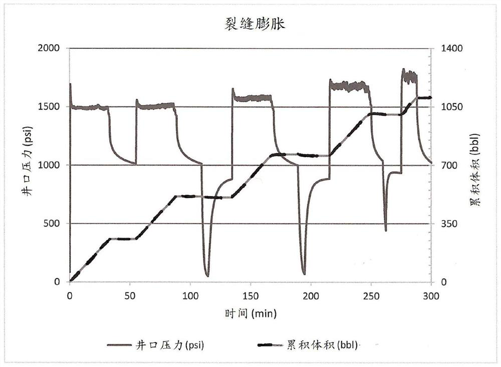
[0031] In a demonstration of one embodiment of the method of the present invention, first, a horizontal fracture was formed at a depth of 1210 feet using 50 bbl of water thickened with guar gum. Fractures were monitored during shut-in for 24 hours and then decompressed. The fracture was then swelled with 100 bbl of water containing a mixture of pre-swollen 1-2 mm and sub-millimeter preformed polyacrylamide PPG particles. Bentonite clay and mineral fibers were added to the PPG blend. An increase in injection pressure was observed during injection, rather than a decrease as expected for short horizontal hydraulic fractures. Fractures were observed during shut-in, and then a series of similar injections of 250 bbl each were performed for a total of up to 1000 bbl. After each stage, the pressure was monitored and then flowback was tested through a fixed choke. At each stage, the injection and shut-in pressures increase, while the flowback volume increases roughly proportional t...

example 2-

[0032] Example 2 - Engineered Tip-Screen Out

[0033] Horizontal fractures formed at 1210 feet were evaluated for potential engineered end screenouts in preformed fractures using a mixture of lost circulation material and conformance control material. Such materials are used in oil fields to seal off thiefzones encountered during drilling or water flood operations and contain particles and fibers ranging in size from microns to centimeters. Typical materials include bentonite clay, crushed walnut shells, mineral fibers, and expanded PPG, among others. The candidate mixture was supplied while expanding the horizontal fracture in stages to 1000 bbl of fluid. figure 2 The pressure response shown shows that the horizontal fractures expand in width at a nominally constant length. A freely expanding horizontal fracture usually exhibits a monotonically decreasing net pressure as the fracture extends, asymptotically approaching the overburden pressure. Instead, the system shows in...


PUM

PropertyMeasurementUnit
particle size distributionaaaaaaaaaa
particle diameteraaaaaaaaaa

Abstract

A method for manipulating hydraulic fracture geometry. In one embodiment, the method includes injecting fracturing fluid into a well to create one or more hydraulic fractures in a subterranean formation, and then substantially draining any fluid in the one or more hydraulic fractures. The method may also include injecting a hydrophilic polymer and one or more cross-linking agents into the well to subsequently form a low density hydrogel, which may then desand only each end of the one or more hydraulic fractures. A working fluid may then be injected into the well to increase the fracture width of the one or more hydraulic fractures without substantially increasing the fracture length. In alternative embodiments, a hydrophilic polymer may be fully cross-linked by the one or more cross-linking agents and injected as pre-crosslinked gel particles (PPGs), which may also de-sand only each end of the one or more hydraulic fractures.

Description

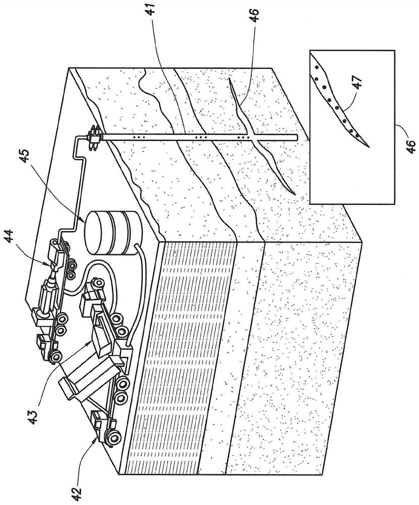
[0001] CROSS-REFERENCE TO RELATED APPLICATIONS [0002] Not applicable. [0003] Statement Regarding Federally Funded Research or Development [0004] Not applicable. technical field [0005] The present invention relates to a method for manipulating hydraulic fracture geometry in a rock matrix. More particularly, the present invention relates to a method for manipulating hydraulic fracture geometry in a rock matrix to optimize energy storage and power generation in a geomechanical pumped hydro storage system, or to improve the production of mineral resources. Background technique [0006] In the oil and gas industry, it is common to encounter hydraulic fractures in various rock formation matrices surrounding wells. For example, hydraulic fractures may be intentionally created during the production of unconventional oil and gas resources, or may even be accidental during drilling operations. In either case, some control over the fracture geometry of these hydraulic fract...

Claims


Application Information

Patent Timeline
Patent Type & Authority Applications(China)
IPC IPC(8): E21B43/267C09K8/68C09K8/88
CPCE21B43/267C09K8/685C09K8/887C09K8/882C09K8/88C09K8/80C09K8/512C09K8/516E21B43/261E21B43/27
Inventor 霍华德·K·史密德斯科特·怀特德米特里·科辛金
Owner QUIDNET ENERGY INC
Learn More