Data synchronization time service system and method of laser radar and inertial sensor

A technology of inertial sensors and laser radars, applied in radio wave measurement systems, satellite radio beacon positioning systems, instruments, etc., can solve problems such as poor bridge detection results, insufficient time synchronization accuracy of IMU and laser radar, etc., to overcome Effects of Insufficient Time Synchronization Accuracy

Active Publication Date: 2022-07-15
SICHUAN INNOVATION RES INST OF TIANJIN UNIV
View PDF17 Cites 2 Cited by
  • Summary
  • Abstract
  • Description
  • Claims
  • Application Information

AI Technical Summary

Problems solved by technology

For example, one of the objectives of the present invention is to provide a synchronous timing method and system for lidar and inertial sensing data, so as to solve the poor detection effect of existing drone detection methods for bridge detection and the time synchronization of IMU and lidar The problem of insufficient precision

Method used


Image

  • Data synchronization time service system and method of laser radar and inertial sensor
  • Data synchronization time service system and method of laser radar and inertial sensor
  • Data synchronization time service system and method of laser radar and inertial sensor

Examples


example 1

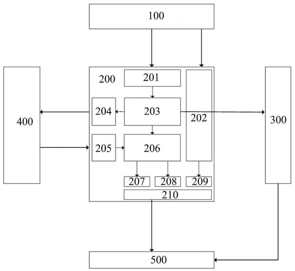
[0078] like figure 1 As shown, it is a schematic structural diagram of an FPGA-based lidar and inertial sensor data synchronization timing system, which includes a GNSS high-precision timing module 100, an FPGA processing unit 200, a lidar 300, an IMU inertial sensor 400 and an industrial computer 500. The GNSS high-precision timing module 100 is connected to the FPGA processing unit 200, the FPGA processing unit 200 is respectively connected to the lidar 300 and the IMU inertial sensor 400, and the industrial computer 500 is respectively connected to the lidar 300 and the FPGA processing unit 200.

[0079] The GNSS high-precision timing module 100 is configured to generate high-precision first PPS pulses and GNSS-NMEA standard messages every second, and transmit them to the FPGA processing unit 200 . The FPGA processing unit 200 is configured to generate a lidar trigger signal (ie, the second PPS pulse) and an IMU trigger signal while receiving the first PPS pulse transmitte...


PUM


Abstract

The invention provides a data synchronization time service system and method for a laser radar and an inertial sensor. The system comprises a satellite time service module, an FPGA processing unit, an IMU, the laser radar and a control unit. The satellite time service module generates a high-precision PPS pulse and UTC time, the FPGA processing unit calibrates the PPS pulse and generates an IMU trigger instruction, synchronous time service of the IMU and the laser radar is controlled through the calibrated PPS pulse and IMU trigger instruction, and corresponding timestamps are collected; and the industrial personal computer analyzes the calibrated laser radar data packet and the calibrated IMU data packet to complete time system alignment of the IMU data and the laser radar data. According to the system and the method, the problems that in the current multi-sensor fusion process, synchronous time service between the IMU and the laser radar and the GNSS is difficult, and the time synchronization precision of multi-sensor data is low are effectively solved.

Description

technical field [0001] The invention relates to the technical field of time synchronization between radar data and inertial sensor data, in particular to a data synchronization timing system of laser radar and inertial sensor and a data synchronization timing method of laser radar and inertial sensor. Background technique [0002] In recent years, collapse accidents of bridges, dams and other buildings have often occurred in our country. Sometimes collapse accidents even cause huge casualties and property losses. Therefore, regular inspection and maintenance of bridges, dams and other buildings is very important. . There are two common methods for detecting cracks and defects on buildings such as bridges: the first is to set up a crane on the bridge to manually enter the bottom or deck of the bridge for close observation and detection of human eyes; A high-resolution camera was used to capture crack images and perform subsequent analysis. The first method has a very high r...

Claims


Application Information

Patent Timeline
Patent Type & Authority Applications(China)
IPC IPC(8): G01C21/16G01S17/86G01S19/25G04R20/02
CPCG01C21/1652G01S17/86G01S19/256G04R20/02
Inventor 黄战华李晓伟潘成王康年
Owner SICHUAN INNOVATION RES INST OF TIANJIN UNIV
Why Eureka
Try Eureka