
Novel low-frequency decoupling unit

A low-frequency, new type of technology, applied in the field of new low-frequency decoupling units, can solve the problems that affect the coverage effect and channel quality of high-frequency radiation units, affect the coverage effect of antennas and channel quality, and seriously block high-frequency radiation units. Coverage effect and channel quality, ensuring coverage effect and channel quality, and less prone to distortion

Pending Publication Date: 2022-07-15
江苏柏菲特精密科技有限公司
View PDF0 Cites 0 Cited by
  • Summary
  • Abstract
  • Description
  • Claims
  • Application Information

AI Technical Summary

Problems solved by technology

[0003] In the process of using the existing antenna, generally two radiation units of different frequency bands and different standards in one antenna will generate strong electromagnetic interference, for example: an antenna contains both high-frequency radiation units and low-frequency radiation units Because the wavelength of the electromagnetic wave radiated by the low-frequency radiation unit is longer, the diameter of the radiation surface radiated by the low-frequency radiation unit is larger than that of the high-frequency radiation unit, and the height of the radiation surface radiated by the low-frequency radiation unit is also higher than that of the high-frequency radiation unit. The height of the radiation surface radiated by the high-frequency radiation unit is high, so that the low-frequency radiation unit shields the high-frequency radiation unit seriously
When the high-frequency radiation unit is excited, the electromagnetic wave radiated by the high-frequency radiation unit will cause scattering on the low-frequency radiation unit, and then a high-frequency induced current will be generated on the low-frequency radiation unit to cause secondary radiation, and the electromagnetic wave of the secondary radiation will be Superimposed with the pattern of the high-frequency radiation unit, the pattern of the high-frequency radiation unit is distorted, which seriously affects the coverage effect and channel quality of the high-frequency radiation unit, which in turn affects the coverage effect and channel quality of the antenna, making it difficult to meet actual application requirements

Method used


Image

  • Novel low-frequency decoupling unit
  • Novel low-frequency decoupling unit
  • Novel low-frequency decoupling unit

Examples


Embodiment Construction

[0020] The technical solutions in the embodiments of the present invention will be clearly and completely described below with reference to the accompanying drawings in the embodiments of the present invention. Obviously, the described embodiments are only a part of the embodiments of the present invention, but not all of the embodiments. Based on the embodiments of the present invention, all other embodiments obtained by those of ordinary skill in the art without creative efforts shall fall within the protection scope of the present invention.

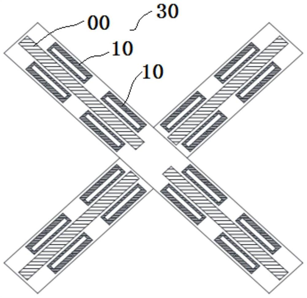
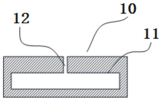
[0021] see Figure 1 to Figure 3 As shown, a new type of low-frequency decoupling unit, the low-frequency decoupling unit is composed of a radiating arm 30; Each side end of the conductor 00 is provided with a resonant structure 10 which is spaced apart from the conductor segment 00 .

[0022] There are several resonant structures 10 , and several resonant structures 10 are spaced at one side of the conductor segment 00 along the len...


PUM


Abstract

The invention discloses a novel low-frequency decoupling unit. The low-frequency decoupling unit is composed of radiation arms. The radiation arm comprises a plurality of conductor sections which are oppositely arranged in pairs according to preset intervals, and the side end of each conductor section is provided with a resonance structure which is separated from the conductor section. The antenna has the advantages that high-frequency induction current can be coupled, distortion of a directional diagram of the high-frequency radiation unit of the antenna is not easily caused, and the coverage effect and the channel quality of the high-frequency radiation unit of the antenna can be ensured.

Description

technical field [0001] The present invention relates to the technical field of communications, and more particularly, to a novel low-frequency decoupling unit. Background technique [0002] In recent years, with the rapid development of communication technology, the antenna technology applied to the communication system also develops in the direction of miniaturization, integration and broadband. At present, in a communication system, one base station is usually provided with an antenna. Due to the limitation of size, each antenna usually has a plurality of radiating units with different frequency bands and different standards inside. [0003] Existing antennas, in the process of use, generally two different frequency bands and different standards of radiation units in one antenna will generate strong electromagnetic interference. For example, an antenna contains both high-frequency radiation units and low-frequency radiation units. , because the wavelength of the electroma...

Claims


Application Information

Patent Timeline
IPC IPC(8): H01Q1/52H01Q1/36H01Q1/50
CPCH01Q1/521H01Q1/36H01Q1/50
Inventor 牛磊超苏瑞年杨琛赵秋利剡义斌
Owner 江苏柏菲特精密科技有限公司
Learn More