Intermittent reinforcing and frame connecting equipment for mattress springs
A technology for connecting equipment and mattresses, applied in the field of spring mattress processing equipment, can solve the problems that cotton affects the insertion of new springs and the clamping gun, the new springs cannot be linked together, and the nailing efficiency is low, so as to improve the nailing efficiency, The effect of improving work efficiency and high degree of automation
- Summary
- Abstract
- Description
- Claims
- Application Information
AI Technical Summary
Problems solved by technology
Method used
Image
Examples
Embodiment 1
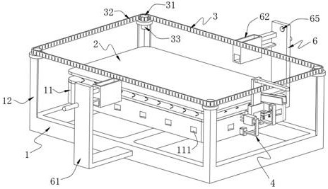
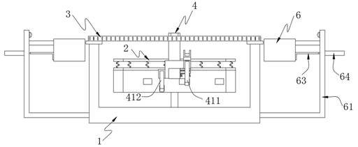
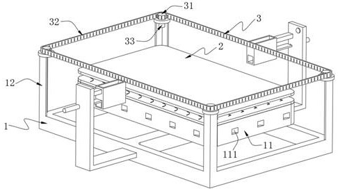
[0051] like Figure 1-5 As shown, a mattress spring intermittent reinforcement and frame connection device includes a frame 1 and a bed bone 2 placed on the frame 1, and further includes:
[0052] a carrying mechanism 3, the carrying mechanism 3 is arranged on the frame 1 along the periphery of the bed frame 2;
[0053] An operating mechanism 4 is mounted on the carrying mechanism 3, the operating mechanism 4 includes a working assembly 41 and a carrying assembly 42 for supporting the working assembly 41, the working assembly 41 includes a working assembly 41 for attaching a The elastic member a is intermittently fed into the feeding unit 411 in the elastic member b on the edge of the bed bone 2, and the connecting unit 412 is used to intermittently connect the elastic member a pushed into the edge of the bed bone 2 with the elastic member b. The working assembly 41 also Including a lifting sleeve plate 413, the feeding unit 411 and the connecting unit 412 are installed on both...
Embodiment 2
[0084] On the basis of Example 1, further, as figure 1 , Figure 5 and Figure 12 As shown, the feeding mechanism 6 includes:
[0085] Two L-shaped support plates 61, and a storage box 62 installed on the L-shaped support plate 61 through connecting plates, the L-shaped support plates 61 are installed on both sides of the frame 1, the storage box 62 Both sides are provided with feeding ports for the elastic member a to pass through;
[0086] The L-shaped feeding plate 63, the hydraulic rod 64 for driving the L-shaped feeding plate 63, and the switch button 65 for controlling the hydraulic rod 64, the L-shaped feeding plate 63 along the The feeding port is slidably arranged at the bottom of the storage box 62 , and the hydraulic rod 64 and the switch button 65 are both installed on the side of the L-shaped support plate 61 .
[0087]It is worth mentioning here that one end of the L-shaped hanging plate 421 of the carrying component 42 has an arc-shaped structure and can be ...
PUM
 Abstract
Description
Claims
Application Information
 - R&D
- Intellectual Property
- Life Sciences
- Materials
- Tech Scout
- Unparalleled Data Quality
- Higher Quality Content
- 60% Fewer Hallucinations
Browse by: Latest US Patents, China's latest patents, Technical Efficacy Thesaurus, Application Domain, Technology Topic, Popular Technical Reports.
© 2025 PatSnap. All rights reserved.Legal|Privacy policy|Modern Slavery Act Transparency Statement|Sitemap|About US| Contact US: help@patsnap.com


