Top end one-way adjusting type elastic outer fixing support fixing arm

A stent-fixed and adjustable technology, applied in external fixators, fixators, medical science, etc., can solve unfavorable bone screw or stylized pin placement, increase bone screw or stylized pin spacing, unfavorable bone fixation, stable fixation, etc. problem, achieve the effect of accelerating fracture healing, preventing delayed union or nonunion, and facilitating nail placement

Pending Publication Date: 2022-07-22
河南科科生物科技有限公司
View PDF1 Cites 0 Cited by
  • Summary
  • Abstract
  • Description
  • Claims
  • Application Information

AI Technical Summary

Problems solved by technology

But this device still has the following deficiencies: the pressure regulating device is located on the slip-fit ​​screw sleeve, which increases the length of the slip-fit ​​screw sleeve, and correspondingly increases the length of the bone screw or the Steiner wire fixed on the fixing rod and the adjusting rod by the needle clip. It is not conduci

Method used


Image

  • Top end one-way adjusting type elastic outer fixing support fixing arm
  • Top end one-way adjusting type elastic outer fixing support fixing arm
  • Top end one-way adjusting type elastic outer fixing support fixing arm

Examples


Embodiment 1

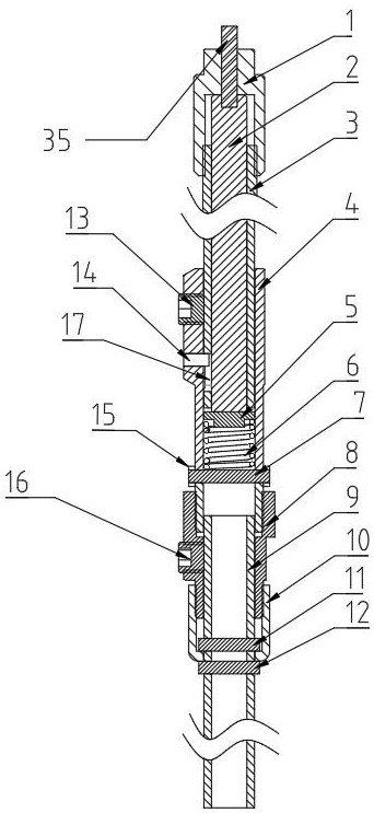
[0058] Embodiment 1, as shown in Figure 1, a top-end one-way adjustable elastic outer fixing bracket fixing arm, the top one-way adjustable elastic outer fixing bracket fixing arm includes: an adjustment rod 3, a stress guide rod 2, a sliding fit The screw sleeve 4, the elastic device, the adjustment device, the fixed rod 9, the fixed rod 9 and the fixed structure of the fixed adjustment rod 3.

[0059] The adjusting device can push the stress guide rod 2 to move along its axial direction, and the specific structure is: including an adjusting nut 1, a scale rod 35, an adjusting nut 1 threadedly connected with the external thread of the adjusting rod 3, a step at the tail, and a stress guide rod 2 The top of the adjusting nut abuts on the steps of the adjusting nut 1; the adjusting nut 1 is threadedly connected with the adjusting rod 3; .

[0060] The stress guide rod 2 can be adjusted slightly in the axial direction relative to the sliding threaded sleeve 4, but cannot be rot...

Embodiment 2

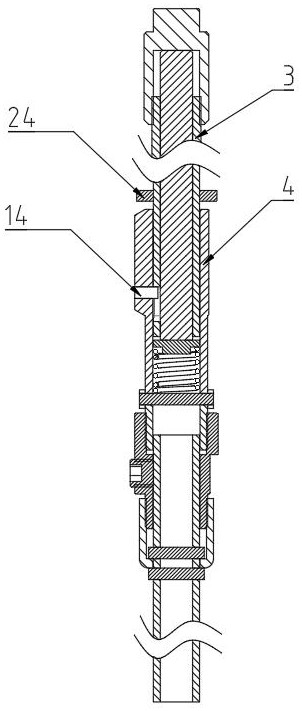
[0064] Embodiment 2, as shown in Figure 2, the difference between this embodiment and Embodiment 1 lies in the fixing structure of the sliding threaded sleeve 4. The fixing structure of this embodiment is: the upper part of the sliding threaded sleeve 4 is radially provided with anti-rotation pins 14, Compatible with the anti-rotation pin hole 17 provided at the lower part of the adjustment rod 3, to prevent the adjustment rod 3 from rotating in the horizontal direction, the upper part of the top of the sliding screw sleeve 4 and the outer wall of the adjustment rod 3 are provided with a tightening screw sleeve 24, and the tightening screw sleeve 24 is connected with the adjustment Rod 3 threaded connection.

Embodiment 3

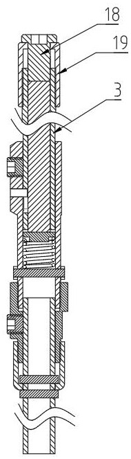
[0065] Embodiment 3, as shown in Figure 3, the difference between this embodiment and Embodiment 1 lies in the adjustment device. In this embodiment, the adjustment device includes an adjustment bolt 18 and a scale sleeve 19. The open end is located outside the adjusting rod 3 , and the other end is provided with an adjusting bolt hole. like Figure 4 As shown, the present application can also provide the spring 6 between the adjusting bolt 18 and the stress guide rod 2, such as Figure 5 As shown, the stress guide rod 2 can also be arranged in two parts, the upper part and the lower part, and the spring 6 is arranged between the upper part and the lower part of the stress guide rod 2 .


PUM


Abstract

The invention discloses a top end one-way adjusting type elastic outer fixing support fixing arm, an outer fixing support comprises an adjusting rod, a stress guide rod, a sliding fit thread sleeve, an elastic device, a fixing rod and a fixing structure for fixing the adjusting rod, the outer fixing support further comprises an adjusting device, and the adjusting device pushes the stress guide rod to move in the axial direction of the stress guide rod. The stress guide rod is located in the adjusting rod, one end of the adjusting rod is in sliding connection with the sliding-fit threaded sleeve, the other end of the adjusting rod is provided with an adjusting device in threaded connection with the adjusting rod, and the sliding-fit threaded sleeve is arranged at one end of the fixing rod in a sleeving mode. When a fractured bone is subjected to axial stress, the bone fracture healing device can stimulate generation of callus at a fractured end, avoid osteoporosis caused by stress shielding of the external fixing frame, accelerate fracture healing, increase the strength of healing sclerotin and effectively prevent delayed healing or non-healing of the fracture.

Description

technical field [0001] The invention relates to an external fixation bracket device for clinical application in orthopaedics, in particular to a fixed arm of an elastic external fixation bracket with one-way adjustment at the top. Background technique [0002] The inventor applied for an application number CN201410064432.9 on 2014.02.20, the name of which is an invention patent for an external fixator elastic device. The fixed clamp block is divided into a needle clamp block and a rod clamp block. The pressure regulating fixed arm is composed of an adjustment shaft, a sliding screw sleeve, an elastic device, a connecting nut, a tightening screw sleeve, and a fixed rod. The sliding sleeve is radially provided with a limit pin, a limit top wire, a pressure regulating pin, an outer ring, an inner ferrule, a pressure regulating nut, and a pressure regulating pin hole. The adjusting shaft is in sliding fit with the sliding threaded sleeve, the connecting nut is threadedly connec...

Claims


Application Information

Patent Timeline
IPC IPC(8): A61B17/66A61B90/00
CPCA61B17/645A61B17/66A61B90/06A61B2090/064
Inventor 宋文超郭智萍叶琳吴学建朱庆棠唐举玉王剑利陈振兵康庆林徐永清郑龙坡陈华常祺宋涛任义军刘国辉郭晓冬王俊文任文杰宋相建李连欣喻爱喜潘振宇李记天焦绍锋王小引王秋霞
Owner 河南科科生物科技有限公司
Why Eureka
Try Eureka