Self-cleaning system

A self-cleaning and cleaning scraper technology, applied in the field of self-cleaning systems, can solve problems such as injury to workers' health, slow work speed, and small scope of application, so as to increase the cleaning area, reduce residues, and improve convenience. Effect

Pending Publication Date: 2022-07-22
江苏肯菲特新能源有限公司
View PDF0 Cites 0 Cited by
  • Summary
  • Abstract
  • Description
  • Claims
  • Application Information

AI Technical Summary

Problems solved by technology

[0003] When cleaning it, it is generally operated manually, but the internal electrostatic field needs to be disassembled for cleaning during operation. The fly ash and sewage during work will directly contact the staff, and will affect the staff. At the same time, manual cleaning is used, the work speed is relatively slow, and the cost is high. However, cleaning with special equipment requires the purchase of special equipment and training of professional workers to operate, and the scope of application is relatively small.

Method used


Image

  • Self-cleaning system
  • Self-cleaning system
  • Self-cleaning system

Examples


Embodiment 1

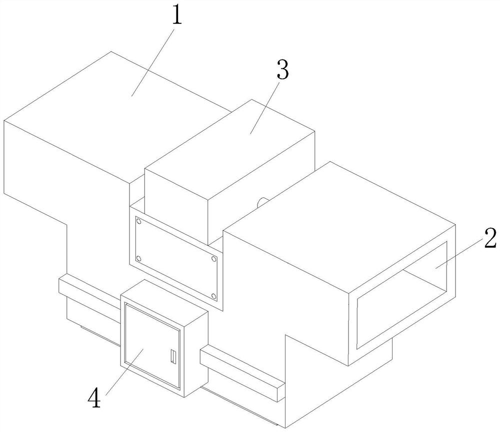
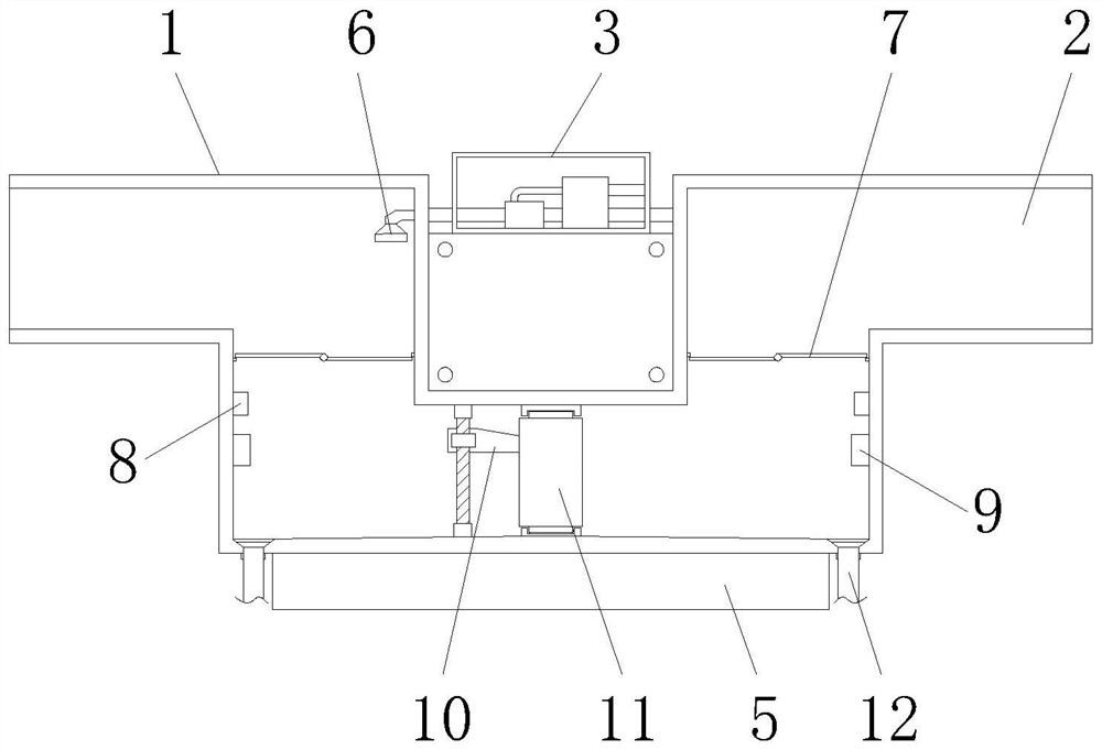
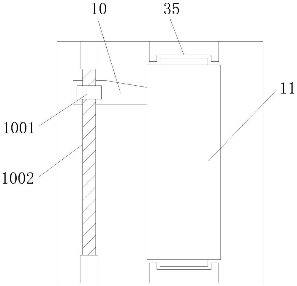
[0031] see figure 1 - Figure 8 , a self-cleaning system, including a purification device 1 and a ventilation duct 2, the lower end of the purification device 1 is fixedly installed with an ultrasonic vibrator 5, the ventilation duct 2 is designed in a "concave" shape, and the ventilation duct 2 is fixedly installed with The water outlet nozzle 6 is movably installed with a sealing valve 7 in the ventilation air duct 2, and the cleaning blade 10 is movably installed in the water outlet nozzle 6. The cleaning blade 10 includes a linkage seat 1001 and a connecting beam frame 1003, and the linkage seat 1001 is connected with internal threads There is a driving link 1002, the connecting beam frame 1003 includes a flushing nozzle 1004 and a flushing joint 1005, the flushing nozzle 1004 is fixedly connected to the outer side of the connecting beam frame 1003, the flushing nozzle 1004 and the flushing joint 1005 communicate with each other, and the cleaning blade 10 is provided with ...

Embodiment 2

[0035] see Figure 9 - Figure 10, a cleaning water tank 3 is fixedly installed on the upper end of the purification device 1, a purification electrostatic field 11 is movably installed in the purification device 1, a mounting bracket 21 is fixedly installed on the outside of the purification device 1, and a winding device 22 is movably installed in the installation bracket 21, and the winding The lower end of the device 22 is fixedly installed with a waterproof curtain 25, the lower end of the purification device 1 is fixedly installed with a protective groove 27, a mounting sensor 28 is fixedly installed in the protective groove 27, and a connecting bracket 23 is fixedly installed in the purification device 1, and the connecting bracket 23 is fixedly installed. A cleaning nozzle 24 is movably installed, a water collecting tank 26 is fixedly installed in the purification device 1 , a drainage pipe 12 is fixedly connected to the lower end of the water collecting tank 26 , a ro...


PUM


Abstract

The invention discloses a self-cleaning system which comprises a purification device and a ventilation air duct, an ultrasonic vibrator is fixedly installed at the lower end of the purification device, a water outlet nozzle is fixedly installed in the ventilation air duct, the ventilation air duct is designed to be of a U-shaped structure, and a sealing valve is movably installed in the ventilation air duct. A cleaning scraper is movably mounted in the water outlet spray head and comprises a linkage seat and a connecting beam frame, a driving connecting rod is in threaded connection with the interior of the linkage seat, the connecting beam frame comprises a flushing spray head and a flushing connector, the flushing spray head is fixedly connected to the outer side of the connecting beam frame, and the flushing spray head is communicated with the flushing connector; and a positioning groove is formed in the cleaning scraper. According to the self-cleaning system, the U-shaped ventilation air duct is additionally arranged, the internal electrostatic field is cleaned through soaking, the internal cleaning effect is improved in cooperation with the ultrasonic vibration device, the anti-overflow valve for preventing internal cleaning water from overflowing is additionally arranged, and the situation that the cleaning water enters the air duct is reduced.

Description

technical field [0001] The invention relates to the technical field of electrostatic dust removal, in particular to a self-cleaning system. Background technique [0002] Electrostatic precipitator means that when the gas containing dust particles in the air is purified, the large particles will first be intercepted and filtered by the primary filter, and then continue to the anode wire (discharge positive electrode) and grounded cathode plate ( After the high-voltage electric field formed between the negative plates), due to the corona discharge generated by the anode, the gas will be corona discharge, and the gas will be rapidly ionized. Under the action of the electric field force, it hits the cathode plate and is adsorbed and deposited on the cathode plate. During the movement, due to the slight potential difference between the nucleus and the cell membrane of the bacteria, it will also be captured and killed by the energy instantly released by the high-voltage charge and...

Claims


Application Information

Patent Timeline
IPC IPC(8): B03C3/74B08B3/02B08B3/12B08B3/14
CPCB03C3/74B03C3/743B08B3/02B08B3/12B08B3/14
Inventor 王千秋
Owner 江苏肯菲特新能源有限公司
Why Eureka
Try Eureka