Double-spindle component machining precision data acquisition device for numerical control machine tool
A technology of machining accuracy and data collection, applied in metal processing equipment, metal processing mechanical parts, manufacturing tools, etc., can solve the problems of inconvenient vibration detection of dual-spindle parts, inconvenient data collection of dual-spindle parts, etc., and achieve convenient adjustment and convenience. The effect of detection
- Summary
- Abstract
- Description
- Claims
- Application Information
AI Technical Summary
Problems solved by technology
Method used
Image
Examples
Embodiment 1
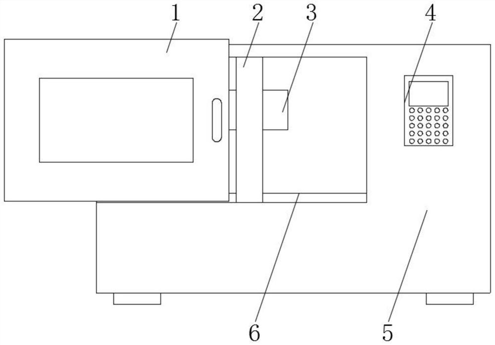
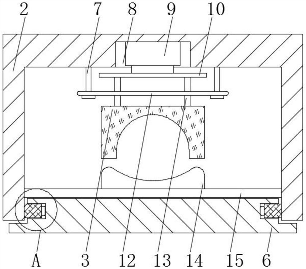
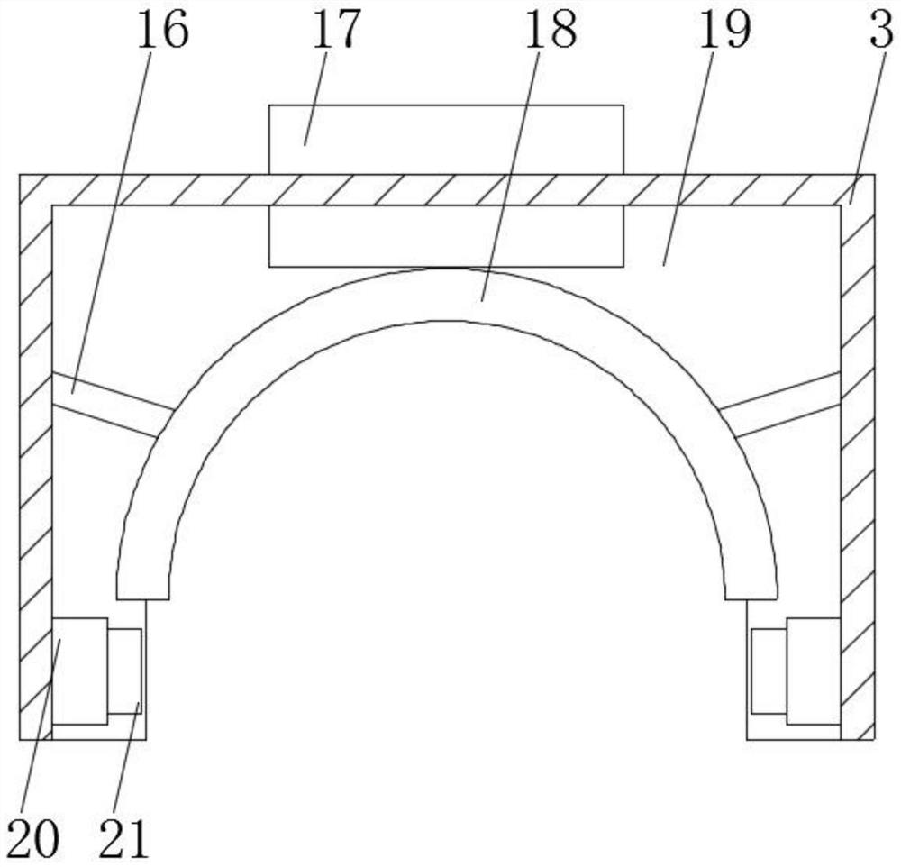
[0033] like Figure 1-5 As shown, the present invention provides a processing accuracy data acquisition device for a dual-spindle component for a numerically controlled machine tool, comprising a protective door 1, a control switch 4, a machine tool body 5 and a workbench 6, and a control switch 4 is fixedly installed on the front of the machine tool body 5, A protective door 1 is slidably connected to the front of the machine tool body 5 and is located on the left side of the control switch 4. The front of the protective door 1 is provided with an observation window. The bottom of the inner wall of the machine tool body 5 is fixedly installed with a workbench 6, and the outer wall of the workbench 6 slides A detection frame 2 is connected. The detection frame 2 is located directly above the workbench 6. A fixing rod 7 is fixedly connected to the inner wall of the detection frame 2. The bottom end of the fixing rod 7 is fixedly connected with a horizontal plate 12. In the dete...
Embodiment 2
[0036] like Figure 1-5As shown, on the basis of Embodiment 1, the present invention provides a technical solution: preferably, the top of the support block 14 is provided with an adjustment groove 24, and the bottom of the inner wall of the adjustment groove 24 is fixedly connected with an elastic member 26, and the elastic member 26 is The other end is fixedly connected with the vibration sensor 23. When the vibration sensor 23 is compressed, the elastic member 26 can be squeezed, so that the vibration sensor 23 can be accommodated by the adjustment groove 24, so that the vibration sensor 23 can better perform the operation of the dual-spindle component. Detection, the inner wall of the adjustment groove 24 is provided with a chute 25, the inner wall of the chute 25 is slidably connected with the guide block 22, the outer wall of the guide block 22 is fixedly connected with the outer wall of the vibration sensor 23, and the vibration sensor 23 can be moved up and down through...
Embodiment 3
[0038] like Figure 1-5 As shown, on the basis of Embodiment 1, the present invention provides a technical solution: the outer wall of the worktable 6 is provided with a guide groove 28, the edge of the inner wall of the detection frame 2 is fixedly connected with a sliding block 27, and the sliding block 27 is The outer wall is slidably connected to the inner wall of the guide groove 28 , the right side of the sliding block 27 is provided with a stability ball 11 , the outer wall of the stability ball 11 is rollingly connected to the inner wall of the guide groove 28 , and the sliding block 27 can be moved on the inner wall of the guide groove 28 . By sliding, the detection frame 2 can be moved back and forth, and the position of the detection frame 2 can be adjusted conveniently. Meanwhile, the stability ball 11 can keep the sliding block 27 stable during the sliding process.
[0039] The working principle of the data acquisition device for the machining accuracy of the dual...
PUM
 Abstract
Description
Claims
Application Information
 - R&D
- Intellectual Property
- Life Sciences
- Materials
- Tech Scout
- Unparalleled Data Quality
- Higher Quality Content
- 60% Fewer Hallucinations
Browse by: Latest US Patents, China's latest patents, Technical Efficacy Thesaurus, Application Domain, Technology Topic, Popular Technical Reports.
© 2025 PatSnap. All rights reserved.Legal|Privacy policy|Modern Slavery Act Transparency Statement|Sitemap|About US| Contact US: help@patsnap.com


