Four-side air inlet adjustable and controllable dry-wet combined cooling tower

A combined cooling and air intake technology, applied in water shower coolers, heat exchange equipment, lighting and heating equipment, etc., can solve problems such as insufficient natural wind draft, and achieve good natural wind draft, good cooling effect, and heat dissipation high performance effect

Active Publication Date: 2022-07-22
SHANDONG HETONG INFORMATION TECH CO LTD
View PDF9 Cites 0 Cited by
  • Summary
  • Abstract
  • Description
  • Claims
  • Application Information

AI Technical Summary

Problems solved by technology

[0004] However, the device arranges the dry-cooling section and the wet-cooling section in a symmetrical or adjacent arrangement, so that the height of the dry-cooling section and the wet-cooling section is equal to the outlet of the tower body, so that when the dry-cooling section or the wet-cooling section operates alone, the tower The draft force under the body is directly shortened by half, resulting in the problem of insufficient natural wind draft force

Method used


Image

  • Four-side air inlet adjustable and controllable dry-wet combined cooling tower
  • Four-side air inlet adjustable and controllable dry-wet combined cooling tower
  • Four-side air inlet adjustable and controllable dry-wet combined cooling tower

Examples


Embodiment 1

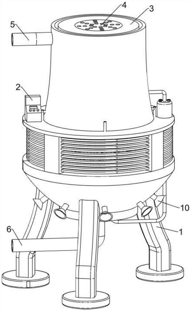
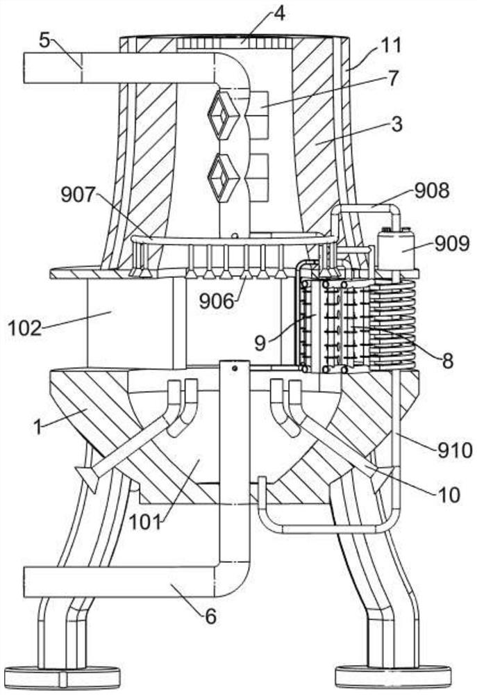
[0027] A dry and wet combined cooling tower with adjustable and controllable air intake from all sides, such as figure 1 and figure 2As shown, it includes a support frame 1, the upper part of the support frame 1 is provided with a water storage cavity 101, the water storage cavity 101 is filled with water, and the upper part of the support frame 1 is provided with four air inlet cavities 102, four The natural air of the air inlet cavity 102 cools the circulating water in the dry cooling mechanism 8 and the wet cooling mechanism 9 by cross-flow cooling. The four air inlet cavities 102 are respectively connected with the water storage cavity 101. Table 2, the upper part of the support frame 1 is fixedly connected with an air extraction sleeve 3, the air extraction sleeve 3 is arranged with a small upper part and a large lower part, the air extraction sleeve 3 is communicated with the water storage cavity 101, and the upper part of the air extraction sleeve 3 is provided with a ...

Embodiment 2

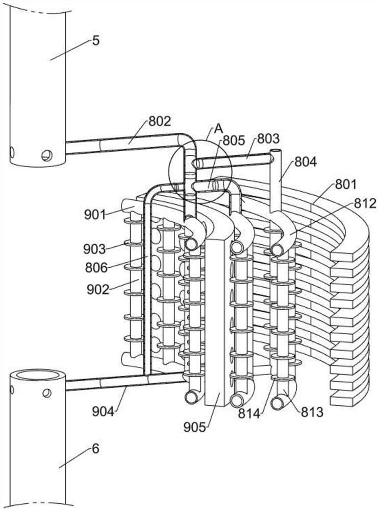
[0030] On the basis of Example 1, as image 3 and Figure 4 As shown, the dry cooling mechanism 8 includes a dry cooling shutter 801, the dry cooling shutter 801 is fixedly connected with the support frame 1, the dry cooling shutter 801 is located in the air inlet cavity 102 on the right side, the dry cooling shutter 801 is electrically connected with the console 2, and the dry cooling shutter 801 is used for In order to regulate the air intake volume of the four air inlet cavities 102, the lower part of the first water inlet pipe 5 is welded with a main water pipe 802, the main water pipe 802 is communicated with the lower part of the first water inlet pipe 5, and the upper side of the outer part of the main water pipe 802 is connected with a first water pipe. Dry cooling branch pipe 803, the outer part of the first dry cooling branch pipe 803 is connected with a second dry cooling branch pipe 804, the lower part of the main water pipe 802 is connected with a first L-shaped p...

Embodiment 3

[0037] On the basis of Example 2, as Image 6 and Figure 7 As shown, it also includes a discharge assembly 11. The upper part of the support frame 1 is provided with a discharge assembly 11 for hot air discharge. The sleeve 1101 is located on the outside of the exhaust sleeve 3. An exhaust cavity 1102 is formed between the exhaust sleeve 1101 and the exhaust sleeve 3. The upper part of the support frame 1 is provided with a number of exhaust holes 1103. The air cavity 1102 is communicated with the four air inlet cavities 102, and several air exhaust holes 1103 are located between the two dry cooling arc pipes 812 on the upper side. The air exhaust cavity 1102 in the discharge assembly 11 and several air exhaust holes The 1103 cooperates to discharge the hot air of this part of the natural wind to achieve a better cooling effect.

[0038] The discharge assembly 11 is used to discharge the natural wind whose temperature is slightly increased through the dry cooling mechanism ...


PUM


Abstract

The invention relates to the field of circulating water cooling equipment, in particular to a dry-wet combined cooling tower with adjustable and controllable four-side air inlet. The technical problem is that a dry cooling section and a wet cooling section are arranged in a symmetrical or adjacent arrangement mode, so that the dry cooling section and the wet cooling section are equal to an outlet of a tower body in height, and the natural wind suction force is insufficient. According to the technical scheme, the adjustable and controllable dry-wet combined cooling tower capable of feeding air from the four sides comprises a supporting frame; four air inlet cavities are formed in the upper portion of the supporting frame in the circumferential direction, the four dry cooling mechanisms are arranged in the circumferential direction and located in the adjacent air inlet cavities correspondingly, and the four wet cooling mechanisms are arranged in the circumferential direction and located in the adjacent air inlet cavities correspondingly. Circulating water in the dry cooling mechanism and the wet cooling mechanism is subjected to transverse flow cooling through natural air of the four air inlet cavities, the better cooling effect is achieved, the better heat dissipation effect is achieved through the dry cooling mechanism, and the better cooling effect is achieved through the wet cooling mechanism.

Description

technical field [0001] The invention relates to the field of circulating water cooling equipment, in particular to a dry-wet combined cooling tower with adjustable and controllable air intake from all sides. Background technique [0002] Some factory equipment usually uses circulating water for cooling and cooling, and then adds the circulating water that absorbs heat into the cooling tower for cooling. The current cooling tower is divided into dry cooler and wet cooling tower. The dry cooling tower needs a large fan for air extraction. The power consumption of large fans is high, resulting in waste of power. Although wet cooling towers do not use fans, they have a large demand for water resources. Therefore, a variety of dry-wet combined cooling towers emerge as the times require. [0003] In the prior art, for example, a dry-wet combined cooling tower with natural ventilation in Publication No. CN110307736A includes a tower body, a dry-wet combined cold section and pipes, ...

Claims


Application Information

Patent Timeline
Patent Type & Authority Applications(China)
IPC IPC(8): F28C1/06F28C1/14F28F21/08F28F25/10
CPCF28C1/06F28C1/14F28F21/085F28F25/10F28C2001/145Y02B30/70
Inventor 张淑贞酆烽耿哲白红光郑述美张毅翟瑞淼
Owner SHANDONG HETONG INFORMATION TECH CO LTD
Why Eureka
Try Eureka