Mold for preventing cracking of castings

A technology of castings and molds, which is applied in the field of molds to prevent cracking of castings, can solve the problems of low production efficiency, slow work of drawing cores, low production efficiency of molds, etc., and achieve the goal of improving production efficiency, improving exhaust effect, and improving processing accuracy Effect

Active Publication Date: 2020-06-26
XIAMEN JIAJIADA MACHINERY
View PDF11 Cites 0 Cited by
  • Summary
  • Abstract
  • Description
  • Claims
  • Application Information

AI Technical Summary

Problems solved by technology

[0007] However, the above three methods all have the problem of low production efficiency. The mold core made of sand core needs to be remade after each processing is completed. The modular mold core needs to be remade after each processing. The mold core is manually reset, and the mold core pulling mechanism is used to prevent the deformation of the casting that has not been completely cooled and formed, and the core pulling work needs to be carried out slowly. Therefore, the existing molds for casting cracking have the limitation of low production efficiency. Improve

Method used


Image

  • Mold for preventing cracking of castings
  • Mold for preventing cracking of castings
  • Mold for preventing cracking of castings

Examples


Embodiment 1

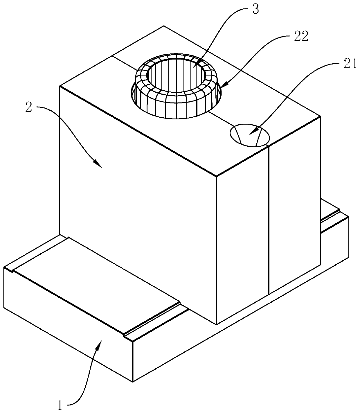
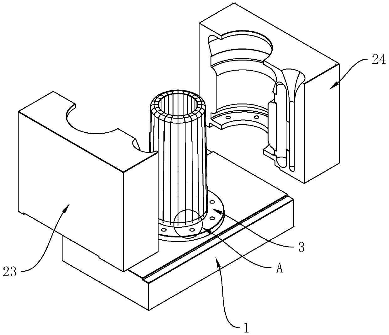
[0052] combine figure 1 with figure 2 As shown, it is a mold for preventing casting cracking disclosed by the present invention, including an outer mold for shaping the contour of the casting and a mold core 3 arranged inside the outer mold for forming the inner cavity of the casting; wherein the outer mold includes The lower mold 1 and the upper mold 2, the mold core 3 is arranged on the lower mold 1, the upper surface of the lower mold 1, the outer wall of the mold core 3 and the inner wall of the upper mold 2 are enclosed to form a cavity for casting molding, wherein, On the upper mold 2, two ends are respectively communicated with the outer wall and the inner wall of the upper mold 2 to be used for pouring the molten material into the runner 21 in the cavity; A riser 22 for air discharge in the mold cavity, the upper end of the mold core 3 stretches out of the riser 22 .

[0053] Among them, the upper mold 2 is divided into a left mold 23 and a right mold 24, and the ru...

Embodiment 2

[0063] Such as Figure 7 As shown, the difference from Embodiment 1 is that the shielding ring 4 is integrally formed with the lower mold 1. Specifically, the upper and lower ends of the lower mold 1 are respectively communicated with the upper and lower surfaces of the lower mold 1 and the inner diameter of the upper port is smaller than that of the lower port. The inner diameter of the stepped groove 12 is provided with a first stop ring 35 on the outer wall of the ring core 3 at the lower end of the core 3. When installing the core 3, only the first stop ring 35 needs to be clamped on the stop ring and make the upper end of the mold core 3 pass through the upper end of the stepped groove 12, and finally use bolts to connect the first limiting ring 35 and the shielding ring 4 together.

Embodiment 3

[0065] Such as Figure 8 As shown, the difference from Embodiment 1 is that the shielding ring 4 is set independently. Specifically, a second stop ring 36 arranged around the ring mold core 3 is provided at the lower end of the mold core 3 , and on the lower surface of the shielding ring 4 There is a card slot 41 set on the same circle center as the shielding ring 4 and communicated with the inner wall of the shielding ring 4. When installing the mold core 3, you only need to place the mold core 3 on the lower mold 1, and then set the shielding ring 4 on the mold core 3 and make the second limit ring 36 clamped in the slot 41, and finally use bolts to fix the blocking ring 4 and the lower mold 1 together.

[0066] Wherein, in this embodiment, the clamping groove 41 can also be provided on the lower mold 1 , or the clamping groove 41 is formed by surrounding the lower surface of the shielding ring 4 and the upper surface of the mold core 3 .


PUM


Abstract

The invention relates to a mold for preventing cracking of castings, and relates to the technical field of molds. The mold for preventing cracking of the castings comprises an outer mold and a mold core, the outer mold comprises an upper mold and a lower mold, and a cavity is formed by enclosing the upper mold, the lower mold and the mold core in a cooperative mode; a runner is arranged on the upper mold, the mold core is made of steel, a cavity is formed in the mold core, the lower end of the mold core is connected with the lower mold, and a plurality of expansion joints distributed around the outer wall of the mold core in the circumferential direction and distributed in a circle are arranged on the mold core; the expansion joints communicate with the upper end surface of the mold core and the outer wall and the inner wall of the mold core; and the mold core is divided into connecting parts and a plurality of elastic gathering parts arranged on the upper sides of the connecting partsand distributed at intervals in the length direction of the connecting parts by the expansion joints. The mold for preventing cracking of the castings has the effect of improving production efficiency.

Description

technical field [0001] The invention relates to the technical field of molds, in particular to a mold used for preventing castings from cracking. Background technique [0002] At present, most hollow or cavity castings are molded by mold casting or mold extrusion. This kind of processing method is a kind of thermal processing. The mold generally includes an outer mold and a mold core, and the outer mold is divided into an upper mold according to needs. And the lower mold, when using the mold for processing, due to thermal expansion and contraction, when the casting is cooled after casting, the inner wall of the casting will shrink after cooling and forming, and the yield of the core is insufficient. If it is not protected, The inner wall of castings is prone to stress concentration, which eventually leads to cracks, resulting in a high defect rate of hollow or cavity castings. Therefore, how to solve the problem of hollow or cavity cracking is a major machining manufacturer....

Claims


Application Information

Patent Timeline
Patent Type & Authority Applications(China)
IPC IPC(8): B22C9/10B22C9/24B22C9/08B22D18/02
CPCB22C9/088B22C9/101B22C9/108B22C9/24B22D18/02
Inventor 王家霖蔡远新汤鑫超陈凤真
Owner XIAMEN JIAJIADA MACHINERY
Why Eureka
Try Eureka