Control method for flexible mutual switching between inverter and power grid

A control method and inverter technology, applied in the field of power grid, can solve the problems of weakening switching overcurrent, large inrush current, prolonging switching time, etc., to avoid repeated charging process, avoid phase error, and reduce motor vibration.

Pending Publication Date: 2022-07-22
SOUTHEAST UNIV
View PDF0 Cites 0 Cited by
  • Summary
  • Abstract
  • Description
  • Claims
  • Application Information

AI Technical Summary

Problems solved by technology

[0004] 1. A reactor is connected in series between the inverter output and the grid, and the reactor is used to weaken the switching overcurrent during the switching process. This method does not require the inverter output voltage to be strictly consistent with the grid voltage amplitude and phase, and a certain The error, but the reactor is usually large in size, seriously occupying the volume of the equipment, and the cost is high
[0005] 2. Adopt the method of "switching first and then switching". During the switching process, the inverter and the grid supply power to the motor at the same time, but in the case of no smoothing reactor, the output voltage of the inverter and the voltage amplitude of the grid must be strictly guaranteed , frequency, and phase are consistent, if the error is too large, the impact current will be large during the switching process, which will damage the inverter
The same is true for switching from grid drive to inverter drive. Generally, the two contactors in the system adopt an interlocking control method, but first, the DC support capacitor needs to be recharged when switching, and the resulting delay causes the phase The error is further expanded, and at the same time, due to the interlocking of the contactor hardware, the switching time is further extended, so there will be a large inrush current

Method used


Image

  • Control method for flexible mutual switching between inverter and power grid
  • Control method for flexible mutual switching between inverter and power grid
  • Control method for flexible mutual switching between inverter and power grid

Examples


Embodiment Construction

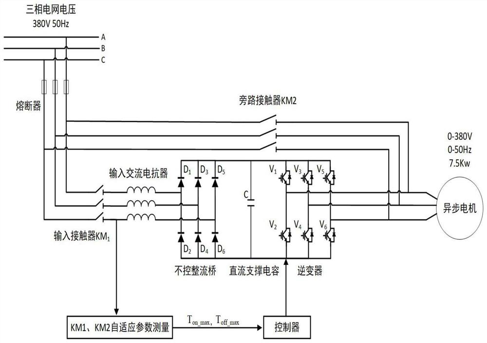
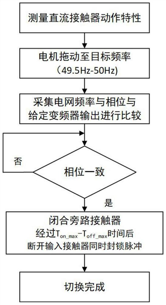
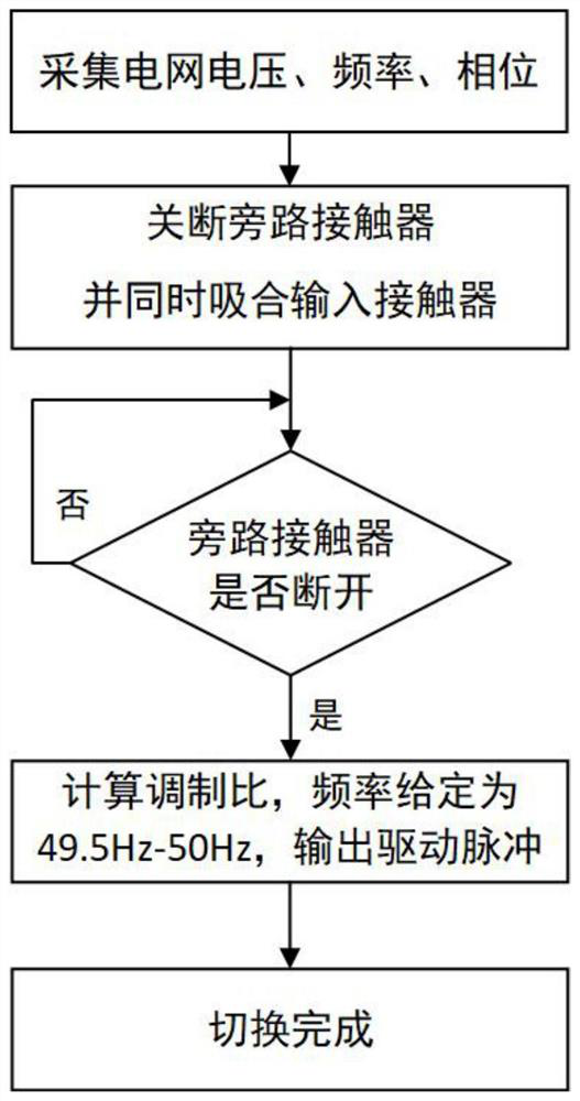
[0032] A control method for flexible mutual switching between an inverter and a power grid. There is no impact during the process of switching a motor from the inverter drive to the grid drive and from the grid drive to the inverter drive, wherein the entire inverter power frequency switching system includes: fuse inverter, inverter input DC contactor, voltage inverter, input AC filter, bypass DC contactor, AC asynchronous motor; A. The flexible switching of the motor from the inverter drive to the grid drive includes the following steps:

[0033] A. The flexible switching of the motor from the inverter drive to the grid drive includes the following steps

[0034] A-1. When the system is powered on and reset, use the controller to measure the mechanical action characteristics of the DC contactor adaptively, that is, control a measurement power supply to act on the electromagnetic coil of the DC contactor through the output I / O port of the controller, and then pass The input po...


PUM


Abstract

The invention discloses a control method for flexible mutual switching of an inverter and a power grid, belongs to the technical field of power grids, and is used for smoothly switching a motor between two working modes of inverter driving and power grid driving. According to the invention, the software interlocking of the bypass contactor and the inverter input contactor is ensured through the self-adaptive measurement of the mechanical action characteristic parameters of the direct current contactor and the auxiliary contact action logic of the contactor, so that the time delay defect of repeated charging of the direct current support capacitor in the switching process is overcome; and the inter-switching time of the inverter and the power grid is minimized, namely flexible inter-switching is realized, and the current impact in the inter-switching process is reduced to the minimum. The method does not need an electric reactor, reduces the number of contactors, and has the advantages of being easy to implement, low in cost, wide in application range and the like.

Description

technical field [0001] The invention relates to a control method for flexible mutual cut-off between an inverter and a power grid, and belongs to the technical field of power grids. Background technique [0002] In actual working conditions, in order to achieve the goal of energy saving, the motor is often required to switch back and forth between the inverter drive and the grid drive, and the inverter is often soft-started when the motor is started to avoid overcurrent at startup. However, there is often an inrush current during the switching process, which will damage the inverter in severe cases. [0003] In the existing related technical solutions, the switching methods mainly include the following: [0004] 1. A reactor is connected in series between the inverter output and the grid, and the reactor is used to weaken the switching overcurrent during the switching process. This method does not require the inverter output voltage to be strictly consistent with the grid v...

Claims


Application Information

Patent Timeline
Patent Type & Authority Applications(China)
IPC IPC(8): H02P27/00H02P27/06H02P4/00H01H47/00
CPCH02P27/00H02P27/06H02P4/00H01H47/001H01H47/002H02P2207/01
Inventor 李浩民时斌
Owner SOUTHEAST UNIV
Why Eureka
Try Eureka