Pneumatic power device

A pneumatic power and pressure technology, applied in the field of pneumatic power devices, can solve the problems of ecological environment destruction, energy depletion, human loss, etc.

Inactive Publication Date: 2022-07-26
冯袖幅
View PDF0 Cites 0 Cited by
  • Summary
  • Abstract
  • Description
  • Claims
  • Application Information

AI Technical Summary

Problems solved by technology

[0002] Due to the development of thermal energy resources, a large number of internal combustion engines and boilers release a large amount of smoke and exhaust gas into the atmosphere every day, accumulating over time our ecological environment has been seriously damaged, c

Method used


Image

  • Pneumatic power device
  • Pneumatic power device

Examples


Embodiment Construction

[0025] The core of the present invention is to provide a pneumatic power device, the structural design of the pneumatic power device can reduce the dependence on thermal energy resources and reduce environmental pollution.

[0026] The technical solutions in the embodiments of the present invention will be clearly and completely described below with reference to the accompanying drawings in the embodiments of the present invention. Obviously, the described embodiments are only a part of the embodiments of the present invention, but not all of the embodiments. Based on the embodiments of the present invention, all other embodiments obtained by those of ordinary skill in the art without creative efforts shall fall within the protection scope of the present invention.

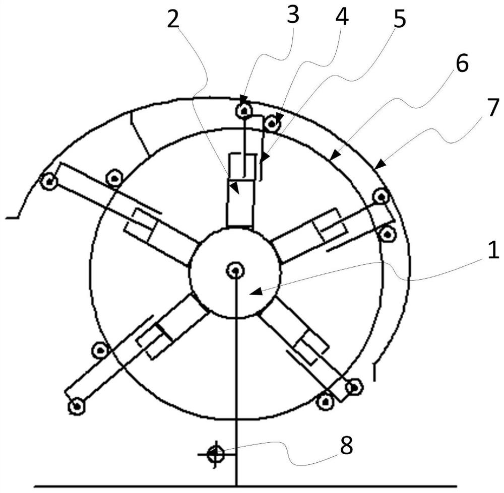
[0027] see figure 1 , figure 1 It is a schematic structural diagram of a pneumatic power device provided in an embodiment of the present invention.

[0028] An embodiment of the present invention discloses a pne...


PUM


Abstract

The invention relates to an air pressure power device which comprises an air storage tank, a driving system and a pressure return system, the driving system comprises at least three driving air cylinders evenly distributed in the circumferential direction of the air storage tank, inner cavities of cylinder bodies of the driving air cylinders are communicated with an inner cavity of the air storage tank, and rotatable top wheels are arranged at the ends, away from the cylinder bodies, of piston rods of the driving air cylinders; a rack is arranged on a piston rod of the driving cylinder; the back pressure system comprises a gear ring, a half-moon ring and a one-way transmission structure, the gear ring and the centers of the driving air cylinders are arranged concentrically in a rotatable mode, the half-moon ring is arranged on the periphery of the gear ring and fixedly connected with the gear ring, a gap between the half-moon ring and the gear ring is gradually increased from the first end to the second end of the half-moon ring, and the rack is in transmission connection with the gear ring through the one-way transmission structure; therefore, the air pressure power device does not depend on existing fuel, but is driven through pressure difference, dependence on heat energy resources can be effectively avoided, emission is reduced, and energy conservation and environmental protection are achieved.

Description

technical field [0001] The invention relates to the technical field of power equipment, in particular to a pneumatic power device. Background technique [0002] Due to the development of thermal energy resources, a large number of internal combustion engines and boilers release a large amount of smoke and exhaust gas into the atmosphere every day. Over time, our ecological environment has been seriously damaged, causing incalculable losses to human beings, and the energy is increasingly depleted. Human production and life will be paralyzed without new energy to replace decades later. Therefore, it is urgent to develop a new energy power device to reduce the dependence on thermal energy resources. SUMMARY OF THE INVENTION [0003] The purpose of the present invention is to provide a pneumatic power device to reduce dependence on thermal energy resources and reduce environmental pollution. [0004] To achieve the above object, the present invention provides the following te...

Claims


Application Information

Patent Timeline
IPC IPC(8): F15B15/06F15B15/08F15B15/20F16H47/02
CPCF15B15/06F15B15/065F15B15/08F15B15/20F16H47/02F16H2047/025
Inventor 冯袖幅
Owner 冯袖幅
Why Eureka
Try Eureka