
Novel needle valve matching part

A coupling and needle valve technology, which is applied in the direction of engine components, charging systems, fuel injection devices, etc., can solve the problem of reducing the service life of the needle valve coupling, can not solve the problem of oil volume under high and low working conditions, and the atomization effect of the needle valve coupling Poor problems, to achieve the effect of prolonging service life, improving atomization effect and quality, and improving work reliability

Active Publication Date: 2022-07-29
CHONGQING HONGJIANG MACHINERY
View PDF10 Cites 0 Cited by
  • Summary
  • Abstract
  • Description
  • Claims
  • Application Information

AI Technical Summary

Problems solved by technology

These two often can only meet the needs of high working conditions, which leads to poor atomization effect of the needle valve assembly when the flow cross-sectional area is too large, low working conditions or idling operation, causing problems such as insufficient combustion, incomplete combustion, etc. It even leads to serious carbon deposits on the head of the needle valve body, resulting in blockage of the nozzle hole and reducing the service life of the needle valve assembly
[0003] In view of the above-mentioned problems, the Chinese patent with the notification number CN102762819B discloses a diesel engine, which discloses an upper and lower multi-nozzle structure for avoiding overlapping nozzle sprays, and indicates that the larger the upper nozzle setting, the better. The patent is only to optimize the combustion chamber and the valve timing mechanism, adding two layers of nozzle holes to avoid atomization overlap, without independent control of the two layers of nozzle holes, and can not solve the problems related to low working conditions caused by the difference in oil quantity between high and low working conditions

Method used


Image

  • Novel needle valve matching part
  • Novel needle valve matching part
  • Novel needle valve matching part

Examples


Embodiment

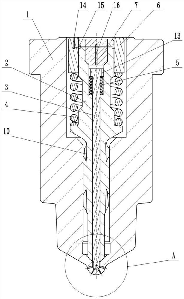
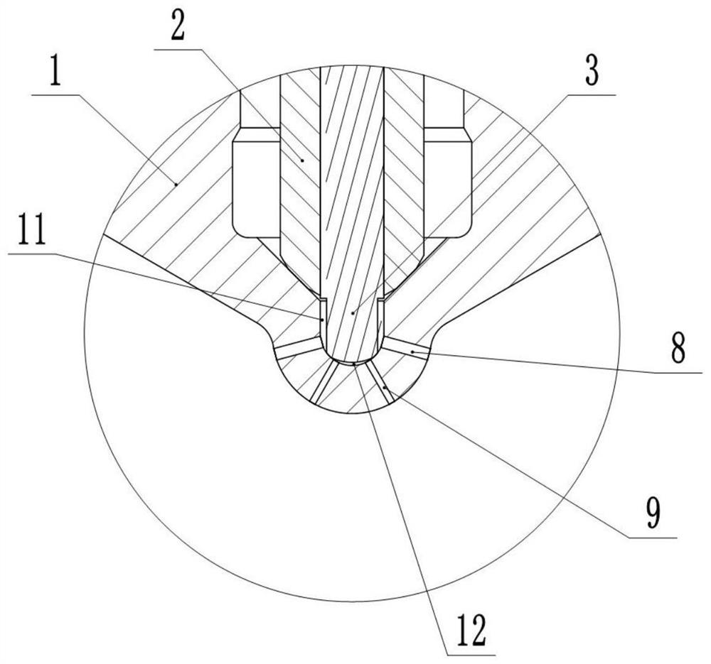
[0027] basically as attached figure 1 Shown: a new type of needle valve coupler, including needle valve body 1, primary valve core 2, secondary valve core 3, pressure regulating spring 4, return spring 5, control sleeve 6 and plug 7, needle valve The body 1 is a hollow structure, the primary valve core 2 is installed in the needle valve body 1, the secondary valve core 3 is installed in the primary valve core 2, the needle valve body 1 and the primary valve core 2, the primary valve core 2 and the primary valve core 2 are installed. The matching pair gap of the secondary valve core 3 is 3 μm to 5 μm. figure 2 As shown in the figure, the bottom of the needle valve body 1 is provided with a pressure accumulating cavity, and there are several first-layer nozzle holes 8 and several second-layer nozzle holes 9 on the outside. The valve core 2 can close the pressure accumulating cavity, and the bottom of the secondary valve core 3 can extend into the pressure accumulating cavity t...


PUM


Abstract

The invention relates to the technical field of needle valve matching parts of internal combustion engines, in particular to a novel needle valve matching part which comprises a needle valve body, a first-stage valve element, a second-stage valve element, a pressure adjusting spring, a reset spring, a control sleeve and a plug, the needle valve body is of a hollow structure, the first-stage valve element is installed in the needle valve body, the second-stage valve element is installed in the first-stage valve element, and a pressure storage cavity is formed in the bottom of the needle valve body. A plurality of first-layer spraying holes and a plurality of second-layer spraying holes are formed in the outer side of the pressure storage cavity, the first-level valve element can seal the pressure storage cavity, the bottom of the second-level valve element can stretch into the pressure storage cavity to seal the second-layer spraying holes, and the first-level valve element and the second-level valve element are adopted to independently control the two layers of spraying holes. The second-level valve element can be closed, only the first-level valve element is opened, and therefore only the first-layer spraying holes are opened, and the oil amount is reduced; when high oil quantity is needed, the two-stage valve element can be opened, so that the two layers of spray holes are opened, and the circulation sectional area is increased by increasing the number of the spray holes.

Description

technical field [0001] The invention relates to the technical field of needle valve couplers of internal combustion engines, in particular to a novel needle valve coupler. Background technique [0002] At present, the main structure of the needle valve coupler used in the internal combustion engine is a simple structure in which a single valve core controls a single layer of nozzle holes. In the process of use, to meet the needs of high working conditions, it is necessary to increase the diameter of the nozzle holes or increase the number of nozzle holes to meet the flow cross-sectional area, and then meet the demand for fuel injection; but in low operating conditions or idling operation, it is necessary to Reduce the diameter of the nozzle holes or reduce the number of nozzle holes to reduce the cross-sectional area of ​​the flow to meet the low oil demand. These two often can only meet the needs of high working conditions, and when the flow cross-sectional area is too lar...

Claims


Application Information

Patent Timeline
Patent Type & Authority Applications(China)
IPC IPC(8): F02M61/10F02M61/18F02M61/16
CPCF02M61/10F02M61/182F02M61/1886F02M61/1893F02M61/16
Inventor 王春文黄威龚元华杨清扈爽彭琦周勇吕枫
Owner CHONGQING HONGJIANG MACHINERY
Learn More