Automatic centrifugal testing machine for elastic element

An automatic centrifugal and elastic element technology, applied in the field of centrifuges, can solve the problems of low test reliability, increased test workload, low work efficiency, etc., and achieve the effects of complete test results, wide test range and high utilization rate

Pending Publication Date: 2022-07-29
CHANGCHUN UNIV OF SCI & TECH +2
View PDF0 Cites 0 Cited by
  • Summary
  • Abstract
  • Description
  • Claims
  • Application Information

AI Technical Summary

Problems solved by technology

[0003] The traditional test method is to place the product on the rotating arm, rotate at a constant speed, and perform wiring test. The work efficiency is low and the test reliability is not high.
In particular, the current inertia switch design is redundant design, multi-angle test requirements, etc., which increases the workload of the test

Method used


Image

  • Automatic centrifugal testing machine for elastic element
  • Automatic centrifugal testing machine for elastic element
  • Automatic centrifugal testing machine for elastic element

Examples


Embodiment 1

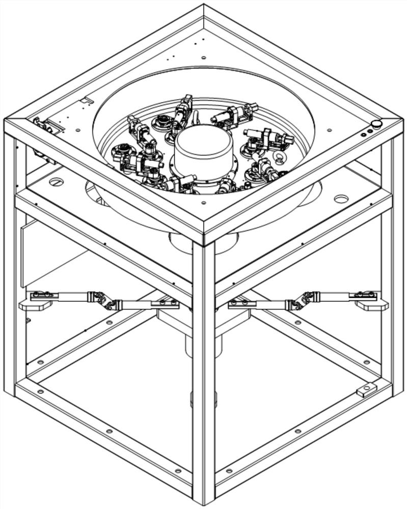
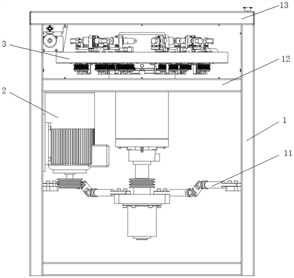
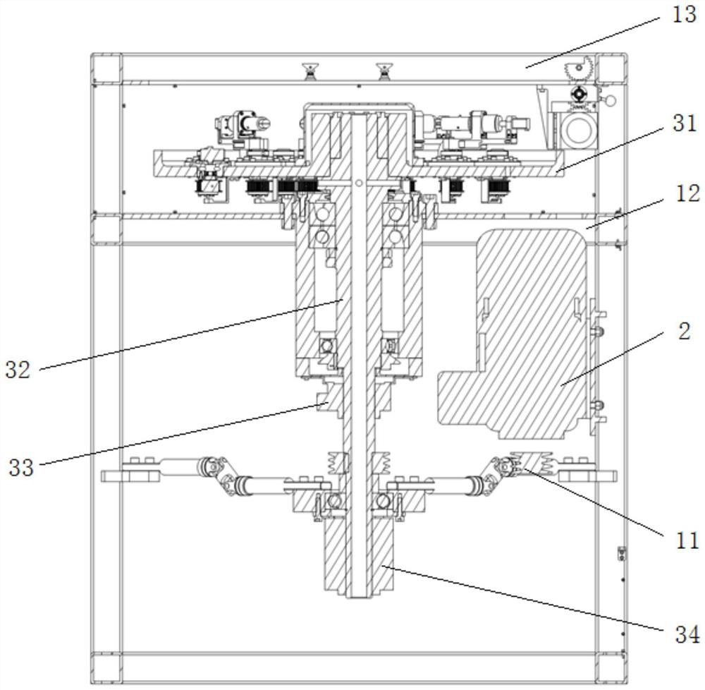
[0055] like Figure 1 to Figure 11 As shown, the component under test assembly 9 is fixed on the No. 2 test unit 8, and the component under test is in a horizontal state at this time, and the centrifugal test is carried out by the present invention:

[0056] S1. Select the centrifugal test radius, install the No. 2 test unit 8 on the test unit connection seat 6 corresponding to the selected centrifugal test radius through the No. 2 quick-change mechanism 84, until all the No. 2 test units 8 are installed in the corresponding test on the unit connection seat 6;

[0057] S2. The worm gear motor 5 drives the test unit connection seat 6 to rotate through the belt transmission mechanism, and drives the No. 2 test unit 8 to rotate synchronously, and then adjusts the axis of the component to be tested and the center of the centrifugal test circle (the center of the turntable 31). The component under test can be adjusted to the following two states:

[0058] S21. The element to be t...

Embodiment 2

[0064] like figure 1 , Figures 12 to 19 As shown, the component under test assembly 9 is fixed on the No. 1 test unit 7, and the centrifugal test is carried out by the present invention:

[0065] 1. Centrifugal test when the component to be tested is in a vertical state

[0066] S1. Select the centrifugal test radius, install the No. 1 test unit 7 on the test unit connection seat 6 corresponding to the selected centrifugal test radius through the No. 1 quick-change mechanism, until all the No. 1 test units 7 are installed on the corresponding test units on the connecting seat 6;

[0067] S2. The push-pull electromagnet 73 extends into the limit slot 76 to limit the position of the U-shaped connecting plate 71 in a vertical state, so that the component to be tested is kept in a vertical state;

[0068] S3. The worm gear motor 5 drives the test unit connection seat 6 to rotate through the belt transmission mechanism, and drives the No. 1 test unit 8 to rotate synchronously, ...


PUM


Abstract

The invention discloses an automatic centrifugal testing machine for an elastic element. The automatic centrifugal testing machine comprises a box body, a control motor, a rotary table assembly, a turbine worm gear motor, a testing unit connecting seat, a first testing unit and a second testing unit, the control motor output shaft is connected with the main shaft, and the rotary table conductive slip ring is installed at the lower end of the main shaft and connected with the box frame through the universal supporting arm. The plurality of test unit connecting seats are uniformly distributed in the circumferential direction and are rotationally connected to the rotary table respectively; the turbine worm gear motor is sequentially connected with each test unit connecting seat through a belt transmission mechanism and is used for driving the test unit connecting seats to rotate; the test unit connecting seat is used for installing the first test unit or the second test unit. The first test unit or the second test unit is connected with the rotary table conductive slip ring through a signal line. According to the invention, two centrifugal test radiuses can be provided, and the centrifugal test of the elastic element in multiple modes can be realized through the two test units.

Description

technical field [0001] The invention belongs to the technical field of centrifuges, relates to an automatic centrifuge, in particular to an automatic centrifugal testing machine for elastic elements. Background technique [0002] The inertia switch is an important mechanism for the normal function and safety of the fuze. The reliability of the inertia switch is an important component to ensure the normal operation of the fuze, and a key component that determines the normal function of missiles and artillery shells. The opening / closing of the inertia switch usually works under the state of large overload G value, and the maximum overload value is 3500g. Therefore, the test of inertia under high overload conditions has become a key test in the manufacturing process. [0003] The traditional test method is to place the product on the rotating arm, rotate at a constant speed, and test the wiring, which has low work efficiency and low test reliability. In particular, the curren...

Claims


Application Information

Patent Timeline
Patent Type & Authority Applications(China)
IPC IPC(8): F42C21/00
CPCF42C21/00
Inventor 田春林曹国华杨晓宇解植文刘伯愚
Owner CHANGCHUN UNIV OF SCI & TECH
Why Eureka
Try Eureka